

Data Fusion at Uspenski Cathedral in Helsinki: Merging TLS and MLS into One Production-Ready Point Cloud
Some structures demand more than a single scanning method can deliver. Uspenski Cathedral, with its storied stone stairs, richly detailed walls, and complex facades, is exactly that kind of subject. Therefore, it became the proving ground for a workflow that combines the best of two worlds: terrestrial laser scanning (TLS) and mobile laser scanning (MLS).
The result is a single, unified, georeferenced point cloud that captures both the millimeter-level precision the cathedral’s architecture demands and the fast, flexible coverage needed to fill in the gaps around it. All this processed in TerraScan and TerraMatch, and publishd live to the web with TerraPointCloud.
Why Combine TLS and MLS?
Every reality capture method has a sweet spot. TLS delivers the highest achievable accuracy, making it the natural choice for features that mattered the most in this project: the cathedral’s stairs and walls. MLS, meanwhile, is built for speed and coverage, making it ideal for bridging gaps between static scan positions and covering surrounding areas where survey-grade precision wasn’t the priority.
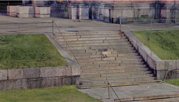
Rather than choosing one method over the other, this project fused both letting each dataset to do what it does best.
Instruments used:
- Zoller+Fröhlich Imager 5016 terrestial laser scanner
- Faro Orbis mobile laser scanner
- Visual targets and South G2 GNSS RTK reciever
Building the Project: A Step-by-Step Walkthrough
Want to run a project like this yourself? Here’s how the Uspenski workflow comes together in TerraScan (from version 026.017), from raw scans to a published, browser-ready model.
Step 1: Create the Project
Start by defining a new TerraScan project with:
- Cloud type: Stationary
- Blocks: Individual scans
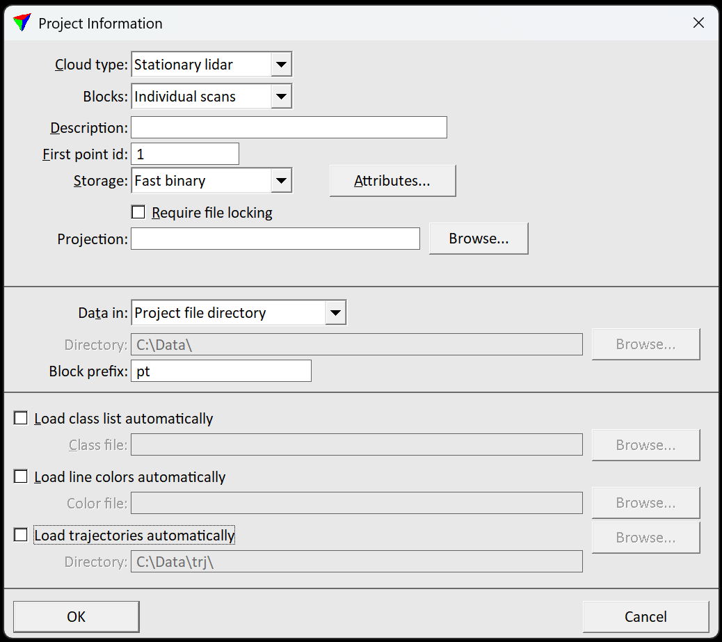
This block-per-scan structure is what makes the rest of the workflow steps so efficient later on.
Step 2: Import and Match the TLS Scans
Import your TLS scans directly. No pre-georeferencing or pre-matching required. TerraScan’s TLS matching workflow is built to handle scans that all have scannin position at the origin of local coordinates, so you can bring raw scan data straight in.
To help the matching process, set rough position accuracy estimates for each scan station:
- Default: 1000 m for XY accuracy, 1000 m for Z accuracay, 180 degrees for angle accuracy
- Tighter, more confident values speed up matching considerably
- Rotation, XY and Z accuracy can all be set independently for each station
Step 3: Link Positions and Set Approximate Locations
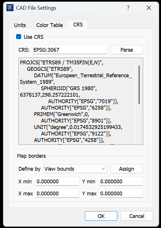
You can accelerate matching further by clicking approximate scan positions directly on a background map. This requires roughly transforming the point clouds closeby the scanning location. Setting this up for example in Spatix takes two steps:
- Set the CRS for your CAD file in Spatix’s CAD File settings
- Add a background map via the Spatix WMS Layer Manger
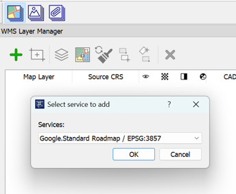
Once positioned, link scan stations that share common features. Shared geometry between neighboring scans produces stronger, more reliable matches. The more overlap between the stations, the better the fit.
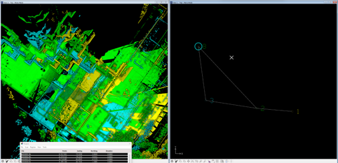
Step 4: Georeference the Terrestial Scans
With matching complete, tie the whole TLS point cloud to real-world coordinates using the Fit Using Targets or any other TerraScan georeferencing tool using measured visual targets as known points.
This step anchors your entire high-accuracy dataset and everything that follows builds on this foundation.
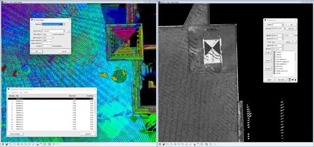
Step 5: Bring the Mobile Data Into Alignment using TerraMatch
MLS data is easiest to process independently first, before fusing it with the TLS cloud. Once the MLS processing in separate CAD instance is done, use following steps in TerraScan and TerraMatch:
- Create new user defined coordinate transformation, which moves the MLS point cloud to closeby the georeferenced TLS point cloud
- Translate and rotate the MLS point cloud and trajectory to roughly match TLS point cloud by hand with TLS points opened as reference points. Point clouds should have less than 10 cm accuracy after this step to have good foundation for matching algorithms.
- Open the initial TLS CAD instance and import MLS points
- In TerraMatch, use Search tie lines and set tool to search features that the TLS and MLS datasets have. For this project plain points, surface lines and vertical walls are used. Save the tie line settings file.
- Use Find tie line match and Apply corrections for points, tie lines and trajectories
- Use Find tie line fluctuation and Apply corrections for points, tie lines and trajectories
Step 6: Clean Up Moving Objects
Cathedral grounds attract people and scans pick up every one of them. TerraScan handles filtering them cleanly:
- Run Assign Groups with Planar points, By tree logic and By density.
- Classify groups that only contain points from a single or just a few scans, as those points are likely to be moving objects.
- Finish the cleanup with Classify Above tool if some groups are visible from multiple scans.
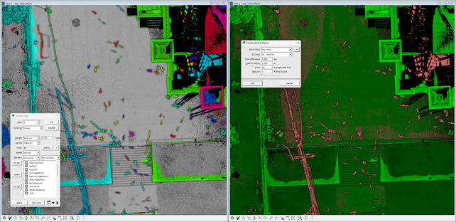
The result is a scene free of pedestrians and all other moving objects as they are classified into noise class. Permanent structure is left untouched.
Step 7: Classify Automatically
Let TerraScan do the heavy lifting. Ground, buildings, vegetation, trees, walls, cars, and poles are all classified automatically with Classify by Best Match tool.
Step 8: Let the Most Accurate Data Win
Now for the fusion itself. Since TLS is inherently more accurate than MLS, set TLS point cloud reliability higher. Then run macro that:
- Deletes MLS points wherever TLS coverage already exists
- Keeps MLS points only in the gaps to expand coverage exactly where TLS didn’t reach
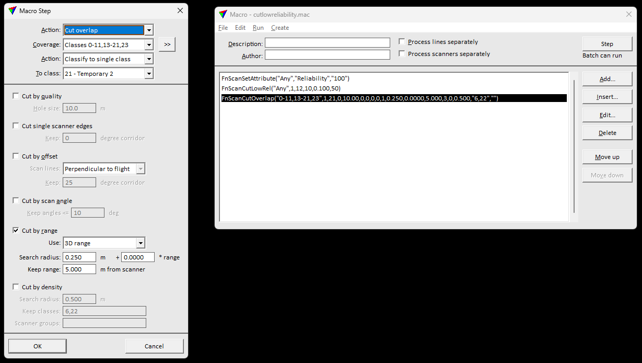
First, run just the first row with different reliability values to MLS and TLS point clouds. One way to do this, is to reopen the point cloud with importing just those lines including MLS first, and then doing the same to just those lines including TLS. Then, running the last two rows for full dataset classifies the low reliability points to overlap when high reliability is available.
This is the heart of the “usable” data fusion approach: instead of two overlapping datasets competing for the same space, you get one clean, non-redundant cloud where every point comes from the best available source.
Step 9: Publish with TerraPointCloud
The finished, fused point cloud is published straight to TerraPointCloud which is viewable on any device, in any browser, with no specialist software required.