

TerraScan User Guide
Working with Projects
Not UAV
A project definition in TerraScan helps to organize the work with a huge point cloud and to automate processing tasks. Basically, it is a method of dividing the whole point cloud data set into smaller, better manageable parts. These smaller geographical regions or blocks should be sized so that the laser data referenced by one block fits into the computer’s RAM. There must be some space left in RAM for processing routines. See Memory usage of loaded points for more information.
TerraScan UAV does not include any project functionality.
A project definition is saved in a TerraScan project file with the extension *.PRJ. It is an ASCII file including:
•header - project settings.
•block names - laser file name and extension as link between the project and the referenced binary files storing the points.
•block boundaries - coordinates of the vertices of each block boundary.
Typical steps for creating a project are:
1. Use Load Airborne Points tool or Read points command to load a subset of points (every 10th, 50th, 100th,...) from all input files that belong to a project. This shows the geographical coverage and location of laser points without providing the full point density.
2. Create block boundaries. There are several tools and methods that support the creation of block boundaries:
•Measure Point Density tool - estimate the amount of points inside a certain area by using a rectangle as sample area.
•Any CAD tool for placing closed elements - place boundary shapes for the blocks. Each block should enclose an area with a manageable number of points. You should use snapping tools to avoid gaps and overlap between neighbouring block boundaries.
•Design Block Boundaries tool - create shapes from a closed line work and get an approximate number how many points are inside each shape.
•Create along centerline command - create blocks along a linear element.
•Create along tower string command - create blocks along a tower string element for a powerline corridor.
•Create along trajectories command - create blocks along trajectories loaded in TerraScan.
•Create grid block boundaries automatically during the import of point files. See Import points into project command.
The result of block boundary creation is always a set of shape elements which include the project area for processing. Each shape should enclose a part of the project area with a number of points that easily fit into the computer’s memory.
3. Close the points loaded in step 1 using Close points command.
4. Select Define Project tool. This opens the TerraScan Project window.
5. Define a new project using New project command.
6. Select all block boundary shapes created in step 3.
7. Add blocks to the project using Add by boundaries command.
8. Save the project definition using Save project as command.
9. Import points from all input files into the project using Import points into project or Import directory commands.
Once the points are imported into the project, you can process the data of the referenced files in batch mode. You can run macros on the project which may include several processing steps. Macros can run in TerraScan but most of the macro actions can also be performed in TerraBatch. See Chapter Macros for detailed information.
Before you process project data in batch mode, you would test the settings of macro actions based on loaded points in order to find the optimal parameter values for the project area. It is also recommended to test a macro on several blocks before you run it on the whole project.
Besides running macros on a project, there are several processing tasks that can be performed on project level. The corresponding commands are included in the pulldown menus of the TerraScan Project window and described in the following sections.
TerraScan Project window
The Project window contains all menu commands for creating and modifying project definitions, managing block definitions, and for running processing steps on project level.
Select the Define Project tool to open the Project window:
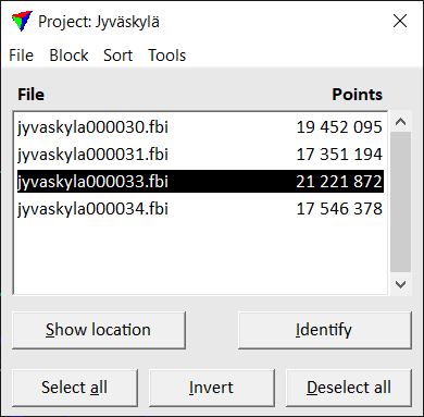
In the file list of the project window, all blocks are listed that belong to the project with the amount of points in the referenced laser binary file. If File locking is active for a project, or if a block binary file is set to be read only, the list also includes information about file locking.
To select a block, click on the name in the list. Press < Ctrl> to select several blocks.
To show the location of a block, select a line in the Project window. Click on the Show location button and move the mouse pointer into a view. This highlights the boundary of the selected block. The highlight appearance can be adjusting the options in Show block location -dialog.
To identify a block, click on the Identify button and place a data click inside a block boundary in a view. This selects the corresponding line in the Project window. Several blocks can be identified if <Ctrl> is pressed while selecting block locations in the view.
You can use the Select all and Deselect all buttons in order to select and deselect all blocks. The Invert button selects all blocks that are previously not selected and deselects previously selected blocks.