

TerraScan User Guide
Design Block Boundaries
Not UAV
 Design Block Boundaries tool creates shape elements that can be used as block boundaries for a TerraScan project. The block boundary creation can start from line or shape elements. If points are loaded in TerraScan, the tool can also compute the amount of points inside each block boundary. Otherwise, the size of the area covered by a block can be used as support for block design.
The line elements used as starting elements for the tool should cross each other in order to create a closed line work for the shape creation. If shape elements are used as starting elements, the tool does not create new shapes. It only computes the amount of points inside or the size of the area covered by the existing shapes.
The tool may also draw labels for the block boundaries that either indicate the amount of points or the size of the area per block. The color of the label indicates whether the amount of points or the size of the area are within a given range. The point count is given in values rounded to million points. The size of the area can be shown using different units and decimal resolutions.
The tool supports significantly the creation of block boundaries for TerraScan projects, especially if the point density is varying in the project area. This is often the case in mobile mapping projects if the driving speed is not constant.
To design block boundaries:
1. (Optional) Load points from the whole project area into TerraScan using Read points command or Load Airborne Points tool. Load only a subset of points if the project area is too big to load all points.
2. Use CAD tools or TerraScan tools to digitize line elements around your project area and to separate the project area into smaller parts.
3. Select the Design Block Boundaries tool.
This opens the Design Block Boundaries dialog:
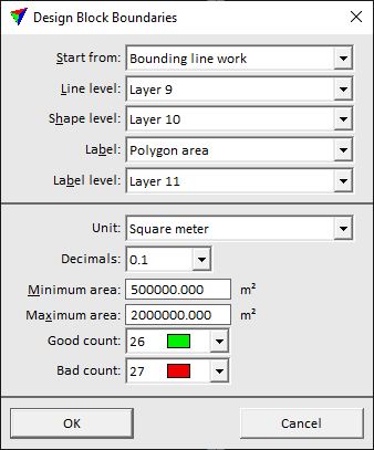
4. Define settings and click OK.
This creates shapes on the given Shape level. If points are loaded in TerraScan, the tool creates text elements on the given Label level.
5. If the amount of points per block is not within the given limits, modify the line work. Run the Design Block Boundaries tool again in order to update the shapes and labels. Continue until the point counts are within the limits.
6. Continue with the Define Project tool in order to add the shapes as block boundaries to a project.
SETTING |
EFFECT |
|---|---|
Start from |
Elements that are used to create block boundaries: •Bounding line work - line elements that form closed areas. •Shapes already drawn - already existing shape elements. |
Line level |
CAD file level on which the line elements are drawn. This is active only if Start from is set to Bounding line work. |
Shape level |
CAD file level on which the shape elements are drawn. The shapes are created if Start from is set to Bounding line work. |
Label |
Defines what is shown with the label for block boundaries: •None - no label is created. •Polygon area - size of the area covered by a block. •Point count - amount of points falling inside the block area. This requires points loaded in TerraScan. |
Label level |
CAD file level on which text elements are drawn. The texts show the amount of points inside a shape area if points are loaded in TerraScan. |
Unit |
Unit for expressing the size of the block area: Square meter, Hectare or Square kilometer. This is active only if Label is set to Polygon area. |
Decimals |
Resolution for expressing the size of the block area. Up to 3 decimals can be displayed. This is active only if Label is set to Polygon area. |
Minimum area |
Minimum size of a block area. This is active only if Label is set to Polygon area. |
Maximum area |
Maximum size of a block area. This is active only if Label is set to Polygon area. |
Load every |
Indicates the subset of points that is loaded into TerraScan. This is active only if Label is set to Point count. |
Minimum count |
Minimum amount of points accepted in one project block. Rounded to million points. This is active only if Label is set to Point count. |
Maximum count |
Maximum amount of points accepted in one project block. Rounded to million points.This is active only if Label is set to Point count. |
Good count |
Display color of a label for shape areas, where the amount of points is within the given Minimum and Maximum count values. Uses the active color table of the CAD file. |
Bad count |
Display color of a label for shape areas, where the amount of points is outside the given Minimum and Maximum count values. Uses the active color table of the CAD file. |