

TerraScan User Guide
Create along tower string
Not UAV
Create along tower string command creates block boundaries along a tower string element. Any linear element can serve as a tower string for this command. The block length is measured along the tower string but a block boundary is drawn at the location of the vertex that is closest within the given block length. The last block ends at the last vertex of the tower string element. The width of the blocks is constant.
Optionally, the command creates text elements that are placed inside each block boundary. The resulting block boundaries and text elements can then be used to define blocks for a project with Add by boundaries command.
The command is most useful for creating blocks for a powerline project. See Chapter Powerlines for more information.
To create blocks along a tower string:
1. Draw a tower string using TerraScan Place Tower String tool or CAD drawing tools.
2. Select the tower string element.
3. Select Create along tower string command from the Block pulldown menu.
This opens the Create Blocks Along Tower String dialog:
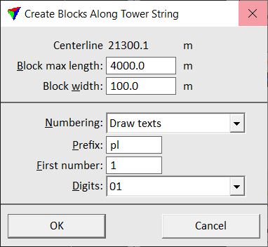
4. Define settings and click OK.
This draws the block boundaries as shapes and, if defined, the text elements into the CAD file. The elements are drawn on the active level using the active symbology settings of the CAD platform.
SETTING |
EFFECT |
|---|---|
Centerline |
The length of the selected tower string is displayed. |
Block max length |
Maximum length of a block. |
Block width |
Width of the blocks. |
Numbering |
Defines labeling of the blocks: None or Draw texts. |
Prefix |
Prefix for text string drawn as label for each block. This is followed by an automatically increasing number. |
First number |
Number of the first block. |
Digits |
Defines the amount of digits for block numbering. |