

TerraModeler User Guide
Display Surface toolbox
The tools in the Display Surface toolbox are used to generate displays from a surface model.
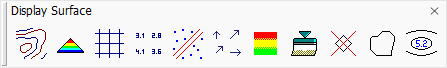
The first six tools generate different visualizations of a surface model. TerraModeler is capable of generating contours, colored triangles, a colored grid, elevation texts, slope arrows, or a shaded surface. The first five display methods can be drawn as permanent elements into the CAD file or as temporary elements which are not saved with the CAD file. A shaded surface is always drawn temporarily.
All six display methods can be updated after modifications to the surface model,using the Update Displays tool. The visualizations can be removed from display by using the Erase Display tool.
Display Boundary tool and Label Peaks and Pits tool create elements which are not updated with the Update Displays tool or removed by the Erase Display tool.
To |
Use tool |
|
|---|---|---|
Display contours |
|
|
Display colored triangles |
|
|
Display colored grid |
|
|
Display elevation as grid spaced texts |
|
|
Display surface model breaklines and elevation points |
|
|
Display grid spaced slope arrows |
|
|
Display coloring by elevation and sun angle |
|
Display Shaded Surface Not Lite |
Update displays after surface modification |
|
|
Erase contours, triangles or grid |
|
|
Display surface model boundary |
|
|
Label local minimum and maximum points |
|
|


Display modes
TerraModeler supports two different modes in which surface displays may be generated.
Write to file mode adds the created elements to the CAD file. This has the disadvantage of increasing the CAD file size quite substantially with some display methods. Very large surface models may result in CAD files which are very cumbersome for processing with CAD tools or for display in dynamic views. The advantages include the option to manipulate the elements using CAD tools and the ability to save the display on a hard disk as a part of the CAD file.
Preview mode recalculates and draws the display elements each time a view is updated. This display mode does neither increase the CAD file size nor consume any RAM space. The mode is supported only by tools which can quickly re-calculate the whole display.