

TerraModeler User Guide
Display Triangles
 Display Triangles tool draws colored triangles for a surface model. You can create a coloring scheme where the color changes according to the surface elevation or according to the slope gradient of the triangles.
To display triangles:
1. Select the Display Triangles tool.
The Display Triangles dialog opens:
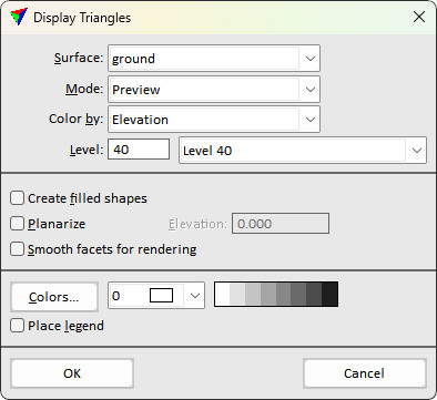
2. Define settings and click OK.
This draws triangles for the selected surface model on the given level.
3. If Place legend is switched on, define the location of drawing the legend with another data point.
Setting |
Effect |
|---|---|
Surface |
Name of the effected surface model. |
Mode |
Display mode for triangles: •Write to file - elements are written and stored in the CAD file. A triangle boundary is drawn in counter-clockwise direction. •Preview - elements are recalculated and redrawn whenever the view is updated. |
Color by |
Attribute used for coloring: •Elevation - elevation value of the triangle determines its color. •Slope - slope gradient of the triangle determines its color. |
Level |
Number of the level in the CAD file on which triangles are drawn. |
Create filled shapes |
If on, triangles are filled with color. |
Planarize |
If on, triangles are drawn as planarized triangles at the given Elevation. |
Smooth facets for rendering |
If on, triangles are displayed with a smoother change in coloring if CAD rendering is applied (No effect in MicroStation CE). |
Inside fence only |
If on, triangles are drawn if their center point is located inside a selected polygon or fence. |
Colors |
Opens the Color scheme dialog. See Creating a color scheme of discrete colors for more information. |
Color list left of the color scheme preview |
Opens the CAD file color table for single color selection. |
Place legend |
If on, a legend for the triangle colors can be placed in the CAD file. This is only active if a color scheme is defined. |
Triangles can be produced automatically in batch mode using the See Utility / Produce triangles command from the Surfaces window.