

TerraModeler User Guide
Display Points and Breaklines
 Display Points and Breaklines tool draws surface model points and breaklines for display. The tool allows visualizing different point and breakline types with different appearance. The tool is useful for inspecting and validating an existing surface model.
To display points and breaklines:
1. Select the Display Points and Breaklines tool.
The Display Points and Breaklines dialog opens:
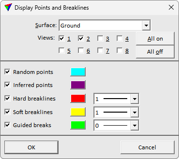
2. Define settings and click OK.
This draws the selected surface model components for display.
3. If Place legend is switched on, define the location of drawing the legend with another data point.
Setting |
Effect |
|---|---|
Surface |
Name of the surface model to display. |
Views |
CAD views where to draw the surface components. Use All on/off buttons to set all selection boxes at once. |
Random/Inferred points, Hard/Soft/Guided breaklines |
If on, the set surface component type is displayed with display color and line type specified on the right. |