

TerraModeler User Guide
Display Contours
 Display Contours tool draws contour lines for a surface model. You can generate quick contours which are suitable for verifying the surface model or higher-quality contours to be plotted on paper.
The tool can also be used to save a contour settings file that is required for producing contour lines automatically in a batch process. The settings file stores all information related to contour lines, labels, and ticks, except the name of the surface model. See Utility / Produce contours for more information.
Contours can be drawn as:
•Curves - smooth elements for which the software computes the curvature. This results in fairly compact elements but can cause contours to intersect each other.
•Line strings - sharp elements suitable for mathematical design surfaces or for surface verification.
•Soft line strings - smooth elements for which TerraModeler computes the smoothing by inserting additional vertices. This results in quite complex elements.
TerraModeler supports three different types of contours. Minor, Basic and Major contours can be distinguished from each other by line color, weight, or style. You can select which of the contour types is displayed and at what intervals. If more than three contour types have to be distinguished, you may use the Modify Contour Symbology tool in order to assign a different level and symbology to contours that are already drawn into the CAD file.
In addition to the contour lines, the software can create labels and ticks for the contours. Further, depressions can be displayed using different symbology settings than for hills. Labels, ticks, and depression line symbology are available in display modes Write to file, but not in Preview mode.
To display contours:
1.Select the Display Contours tool.
The Display Contours dialog opens. Define settings for contour generation.
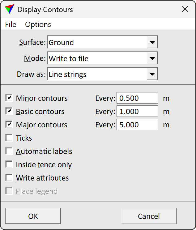
2.Define settings for the symbology of contour lines, labels, and ticks. This can be done using commands Contour options, Contour label options, and Contour tick options from the Options pulldown menu in the Display contours dialog.
OR
3.Load a previously saved settings file into the dialog using the Load settings command from the File pulldown menu.
4.(Optional) Save the settings into a file on a hard disk by using the Save settings As command from the File pulldown menu.
Click Cancel to the Display contours dialog if you just want to save a contour settings file for automatic contour line production.
5.Click OK to the Display contours dialog.
6.If Place legend is switched on, define the location of drawing the legend with a data click.
The contours for the selected surface model are displayed.
Setting |
Effect |
|---|---|
Name of the effected surface model. |
|
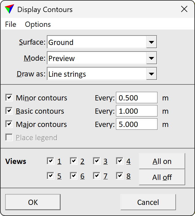
Display mode for contour lines: •Write to file - elements are written and stored in the CAD file. •Preview - elements are recalculated and redrawn whenever the view is updated. |
|
Element type of the contour lines: •Curves - smooth elements for which the software computes the curvature, may overlap each other, compact elements. This is only active if Mode is set to Write to file. •Line strings - sharp elements, suitable for preview. •Soft line strings - smooth elements for which TerraModeler computes smoothing, best quality, large elements. This is only active if Mode is set to Write to file. |
|
If on, minor contours are drawn at Every distance. |
|
If on, basic contours are drawn at Every distance. |
|
If on, major contours are drawn at Every distance. |
|
If on, ticks are drawn along contour lines. This is only active if Mode is set to Write to file. |
|
If on, labels are drawn along contour lines. This is only active if Mode is set to Write to file. |
|
If on, contours are displayed only inside a selected polygon or fence. This is only active if Mode is set to Write to file. |
|
If on, the software writes the contour elements in a way that enables the update of the contours using the Update Displays tool and the removal of contours using the Erase Display tool. This is only active if Inside fence only is switched on. |
|
If on, a legend for contour line symbology is placed. This is only active if Color by is set to Elevation in the Contour options dialog. |
|
Switch on the CAD file views in which the contours should be visible. This is only active if Mode is set to Preview. Use the All on or All off buttons in order to switch on/off the visibility for all views. |
Contour options define symbology settings for contour lines, such as level, coloring, line style, and line weight for the different contour types. They can also limit the contour display to specific domains or an elevation range, define the minimum areas for closed contours, or influence the way of contour line generation.
To define contour options:
1. Select Contours command from the Options pulldown menu in the Display contours dialog.
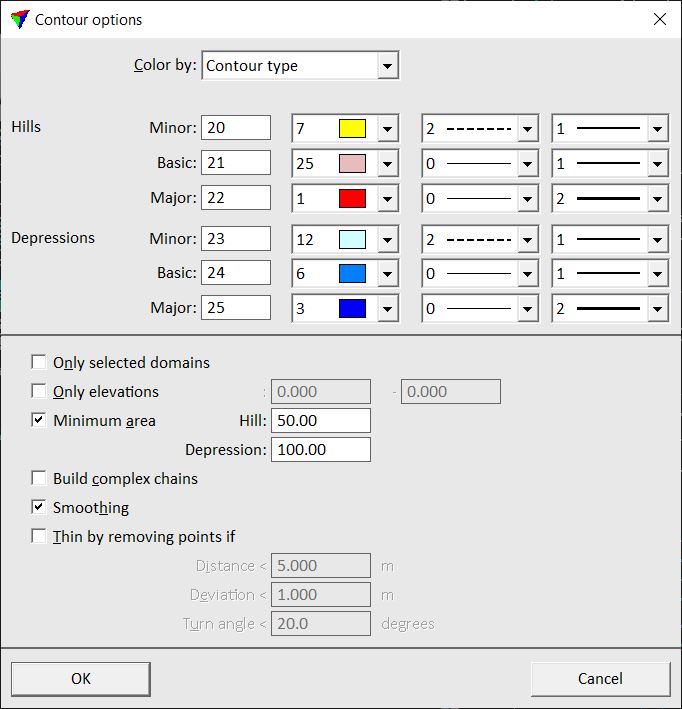
The Contour options dialog opens:.
2. Define settings and click OK.
Setting |
Effect |
|---|---|
Color by |
Contour line coloring method: •Contour type - different colors according to the type of the contour line. •Elevation - a coloring scheme is used for coloring contour lines according to their elevation value. |
Colors |
Color scheme for coloring contours by their elevation value. The color scheme is defined using the Define button. See Creating a color scheme of discrete colors for information about how to create a coloring scheme. Only active if Color by is set to Elevation. |
Minor |
Level, color, line style and line weight for minor contours of hills/depressions. |
Basic |
Level, color, line style and line weight for basic contours of hills/depressions. |
Major |
Level, color, line style and line weight for major contours of hills/depressions. |
Only selected domains |
If on, contours are only drawn for domains for which the Draw contours option is switched on. See Define Domains tool for more information. |
Only elevations |
If on, contours are drawn only for the given elevation range. |
Minimum area |
A closed contour line is not drawn, if the enclosed surface area is smaller than Minimum area. Separate settings for Hills and Depressions. Helps to leave out unnecessary detail. |
Build complex chains |
If on, contours are drawn as complex chains or as complex shapes. |
Smoothing |
If on, contour vertices are slightly adjusted to produce smoother lines. If off, contours pass through triangle edges at mathematically correct positions which may result in jagged contour lines. |
Thin by removing points if |
If on, some of the computed contour vertices may be left out. This helps to minimize the CAD file size when creating contours for large surface models. |
Distance |
A vertex can be left out if the distance between the previous and the next remaining vertex is smaller than this value. Only active if Thin by removing points if is switched on. |
Deviation |
A vertex can be left out if it is closer than this distance value to the line segment connecting the previous and the next remaining point. Only active if Thin by removing points if is switched on. |
Turn angle |
A vertex can be left out if the contour direction changes less than this value at the vertex location. Only active if Thin by removing points if is switched on. |
Contour label options define the position of contour labels in relation to the contour lines, as well as their symbology settings, and their text format.
To define contour label options:
1. Select Contour labels command from the Options pulldown menu in the Display contours dialog.
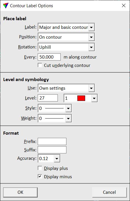
The Contour Label Options dialog opens:
2. Define settings and click OK.
setting |
Effect |
|---|---|
Label |
Defines the contour line type(s) for labeling: All contours, Major and basic contours, or Major contours only. |
Position |
Location where label text elements are placed along a contour line: •Above contour - above the contour line at specified intervals. •On contour - overlapping the contour line at specified intervals. •Below contour - below the contour line at specified intervals. •At contour start - at the start point of a contour chain. |
Rotation |
Rotation of the label text element: •Uphill - label is readable when looking uphill. •Downhill - label is readable when looking downhill. •North up - label is readable when looking in north direction. |
Every |
Distance between consecutive contour labels. Given in meters along the contour. |
Cut underlying contour |
If on, the contour line is cut under the label text element. On Bentley CAD platforms, the line under a label text is drawn as a construction class element. You can use view attributes to control the visibility of the lines under label texts. Further, you can use filtered selection in order to select and delete the lines under label texts. |
Use |
Defines level and color settings for contour labels: •Contour level and color - a label is drawn using level and color of its contour line type (major, basic, or minor). •Own settings - all labels are drawn using the same level and color assigned to labels. |
Level |
Level and color of contour labels. This is only active if Use is set to Own settings. |
Style |
Line style of contour labels. This is only active if Use is set to Own settings. |
Weight |
Line weight of contour labels. This is only active if Use is set to Own settings. |
Prefix |
Prefix added at the beginning of each contour label. |
Suffix |
Suffix added at the end of each contour label. |
Accuracy |
Number of decimals shown in contour labels. |
Display plus |
If on, the plus sign is displayed for positive elevations. |
Display minus |
If on, the minus sign is displayed for negative elevations. |
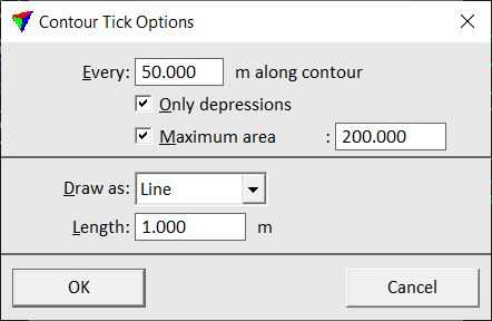
Contour tick options define the position of ticks in relation to the contour lines, as well as the format of the ticks.
To define contour tick options:
1. Select Contour ticks command from the Options pulldown menu in the Display contours dialog.
The Contour Tick Options dialog opens:
2. Define settings and click OK.
settings |
Effect |
|---|---|
Every |
Distance between consecutive contour ticks given in meters along the contour. |
Only depressions |
If on, ticks are drawn only for closed depressions. |
Maximum area |
If on, ticks are drawn only for closed depressions smaller than a given area. |
Draw as |
Shape of ticks: Line or Triangle. |
Length |
Length of the tick line or triangle. |