

TerraModeler User Guide
Display Elevation Texts
 Display Elevation Texts tool draws a grid of labels which display the surface elevation. The exact location of the elevation can be marked by a point marker or by the decimal point of the elevation text.
To display elevation texts:
1. Select the Display Elevation Texts tool.
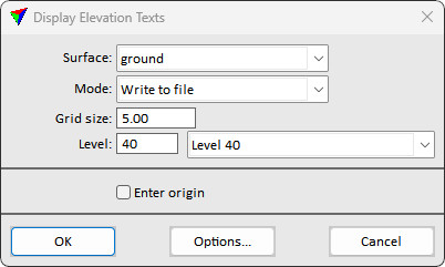
The Display Elevation Texts dialog opens:
2. Define settings.
3. (Optional) Click on the Options button in order to open the Elevation text settings dialog and define settings for elevation label symbology.
4. Click OK to the Display elevation texts dialog.
5. If Enter origin is switched on, enter the origin point of the grid with a data click.
This draws elevation texts for the selected surface model on the given level.
Setting |
Effect |
|---|---|
Surface |
Name of the effected surface model. |
Mode |
Display mode for elevation texts: •Write to file - elements are written and stored in the CAD file. |
Grid size |
Distance between elevation text locations. |
Level |
Number of the level in the CAD file on which elevation texts are drawn. |
Enter origin |
If on, you can enter the origin point of the grid with another data point. If the point is inside the surface area, an elevation text is drawn at this location. |
Options |
Opens the Elevation Text Settings dialog. See Elevation text settings for more information. |
The Elevation Text Settings dialog defines the symbology and other display options for elevation texts created by the Display Elevation Texts tool.
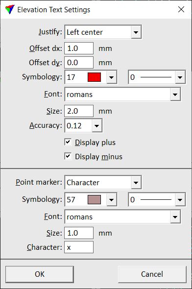
Setting |
Effect |
|---|---|
Justify |
Location of the placement point (= point of elevation measurement): •Left, Center, Right | Top, Center, Bottom - placement point location relative to the label text box. •Decimal point - placement point is located on the decimal point. |
Offset dx |
Offset between the placement point and the label in x (left-right) direction. Given in millimeters on paper. Not active if Justify is set to Decimal point. |
Offset dy |
Offset between the placement point and the label in y (up-down) direction. Given in millimeters on paper. Not active if Justify is set to Decimal point. |
Symbology |
Color and line weight of the elevation text. Uses the CAD file color table and line weights. |
Font |
Font type of elevation texts. Uses font types available in the CAD platform. |
Size |
Text size of elevation texts. Given in millimeters on paper. |
Accuracy |
Number of decimals of elevation texts. |
Display plus |
If on, the plus sign is displayed for positive elevations. |
Display minus |
If on, the minus sign is displayed for negative elevations. |
Point marker |
Type of the placement point marker: •None - no point marker is drawn. •Character - a given character is drawn as point marker. •Zero length line - a line element of zero length (= point) is drawn as point marker. |
Symbology |
Color and line weight of the point marker. Uses the CAD file color table and line weights. This is only active if Point marker is set to Character or Zero length line. |
Font |
Font type of the point marker character. Uses font types available in the CAD platform. This is only active if Point marker is set to Character. |
Size |
Text size of the point marker character. Given in millimeters on paper. This is only active if Point marker is set to Character. |
Character |
Character used as point marker symbol. This is only active if Point marker is set to Character. |
Weight |
Weight of the point marker zero length line. Uses CAD file line weights. This is only active if Point marker is set to Zero length line. |