

TerraModeler User Guide
Modify Contour Symbology
Not Lite
 Modify Contour Symbology tool modifies the symbology of contour lines that are already drawn in the CAD file. It can also move contour lines to another level in the CAD file. The contour lines have to be created with Mode set to Write to file in the Display Contours tool in order to apply the tool.
The tool may be useful, for example, if contour lines need to be distinguished into more than three types that are supported by the Display Contours tool.
To modify the symbology of contours:
1. Select the Modify Contour Symbology tool.
This opens the Modify Contour Symbology dialog:
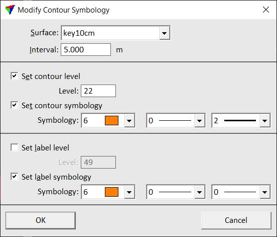
2. Define settings and click OK.
Setting |
Effect |
|---|---|
Surface |
Name of the effected surface model. |
Interval |
Interval of contour lines that are modified. |
Set contour level |
If on, the contour lines are moved to the given CAD file Level. |
Set contour symbology |
If on, the color, style and weight of the contour lines are modified to the given Symbology. Uses the active color table of the CAD file, and CAD file line styles and weights. |
Set label level |
If on, the contour labels are moved to the given CAD file Level. |
Set label symbology |
If on, the color, style, and weight of the contour labels are modified to the given Symbology. Uses the active color table of the CAD file, and CAD file line styles and weights. |