

TerraScan User Guide
Place Tower
Not Lite, Not Spatix
 Place Tower tool lets you place a tower model. The shape of the tower has to be defined in Powerlines / Tower types category of TerraScan Settings. A tower model is drawn as Bentley cell element into the CAD file.
Towers are placed manually based on the tower type definition, an activated tower string element, and laser points. Tower placement can be supported by view arrangement and display options, for example by using the View Tower Spans tool. A typical setup may include views for displaying the span and the tower in (rotated) top views, the tower and the tower tip in cross section views.
The placement of towers with the Place Tower tool is straightforward and includes placing the base point, the tip point, and the end point(s) of the cross arm(s). The XY location of a tower is defined by the vertex of the tower string element. Classified laser points loaded in TerraScan can be used to fix the tower’s base point elevation to the ground.
In addition to the simple tower type models that are defined in the TerraScan Settings, a more complex tower template can be created. Template creation may start from an already vectorized, simple tower model. Then, tools from the Vectorize Towers toolbox can be used to add, for example, more complex cross arms to the tower cell element. See Creating a tower template for more information about how to define a tower template.
To place a tower model:
1. Activate a tower string element using Activate Powerline tool.
2. Select the Place Tower tool.
This opens the Place Tower dialog:
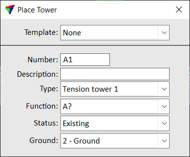
3. Define settings.
SETTING |
EFFECT |
|---|---|
Template |
Use of a template for tower placement: •None - no template is used. •Identify - the tower model that is selected with the next data click is set as active template. •Active - tower models are placed using the active template. |
Number |
Tower number. The number may be preceded with alphanumerical characters. This can be used in reports created with the Export Powerline tool. |
Auto increase |
If on, tower numbers increase automatically while placing towers. |
Description |
Text field for typing a description for the tower. This can be used in reports created with the Export Powerline tool. |
Type |
Type of the tower. Defined in Powerlines / Tower types category of TerraScan Settings in the Description field. |
Function |
Function of the tower. Defined in Powerlines / Tower functions category of TerraScan Settings in the Description field. |
Status |
Status of the tower. Defined in Powerlines / Tower statuses category of TerraScan Settings in the Description field. |
Ground |
Point class used to derive the tower’s base point elevation. This is only used if the base point is placed in a top view. |
4. Move the mouse pointer into a view.
A line is displayed at the location of the tower defined by a vertex of the tower string. In a section view, the base point can be moved in elevation.
5. Define the base point of the tower with a data click.
If the base point is defined in the top view, the elevation is derived from the laser points according to the Ground setting in the tool’s dialog. In a section view, the elevation is defined by the data click.
6. Move the mouse pointer in a section view, preferable a view showing the tip of the tower.
A dynamic preview of the tower center is displayed.
7. Define the tip of the tower with a data click in the section view.
A dynamic preview of the first cross arm is displayed.
8. Place the end point of the first cross arm with a data click in the section view.
9. If the tower model defines additional cross arms, repeat step 8 for all cross arms.
After placing the end point of the last cross arm, the placement of the tower is finished. If Auto increase is switched on in the Place Tower dialog, the number is increased.
Use the list of the View Tower Spans tool to display the next tower. You may define new settings for the next tower in the tool’s dialog and continue with step 4.
While placing a tower model, you can undo step-by-step with reset clicks.
A tower template can be created to place towers with a more complex shape as it can be defined in TerraScan Settings. The template defines the position, length and shape of the cross arms of the tower.
To create and place a tower template:
1. Place one simple tower model using Place Tower tool.
2. Modify the model using Add Cross Arm tool or other Vectorize Towers tools.
3. Select the Place Tower tool.
4. Set Template to Identify.
5. Select the tower model with a data click.
This sets the selected tower model as active template.
You can continue with placing the first tower using the template. Follow the steps 4-7 described above for placing the tower’s base point and tip.
6. The position and length of the cross arms is defined by the template. Confirm the placement of the tower model with another data click in the section view.