

TerraScan User Guide
Powerlines / Tower types
Tower types category in Powerlines folder contains a list of user-defined tower types. The tower type determines the general design of a tower, including the number, position and length of cross arms and attachments.
The values defined for the tower height as well as position and length of cross arms and attachments do not have to be exact if towers are placed with the Place Tower tool using no template. For placing towers using templates the accuracy of the values determine how well a template fits to the real towers design.
It is recommended to enter a text in the Description fields of Tower Type and Tower Type Cross Arm dialogs, because the editing tools for powerline processing refer to this field. The other descriptive information is mainly used in reports. See Chapter Powerlines for more information about powerline processing.
You can Add, Edit, and Delete tower types by using the corresponding buttons in the Settings dialog. You can Add, Edit, and Delete cross arms and attachments for a tower type by using the corresponding buttons in the Tower type dialog.
To add a new tower type:
1. Open the Tower types category in the Powerlines folder.
2. Click Add in the Settings dialog.
The Tower Type dialog opens:
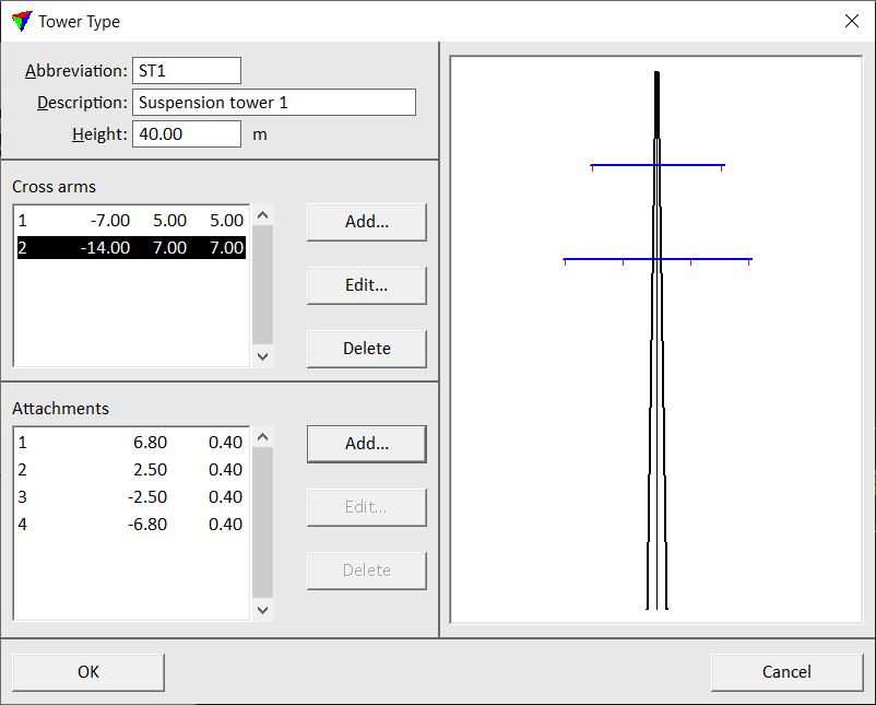
3. Define Abbreviation, Description and Height values.
SETTING |
EFFECT |
|---|---|
Abbreviation |
Abbreviation of the tower type. |
Description |
Description of the tower type. |
Height |
Height of a tower. |
Cross arms |
List of cross arms for this tower type. Use buttons next to the list to Add, Edit, and Delete cross arms. |
Attachments |
List of attachments per cross arm. Select a cross arm and use buttons next to the list to Add, Edit, and Delete cross arms. |
4. Click Add in the Tower Type dialog in order to add a cross arm.
This opens the Tower Type Cross Arm dialog:
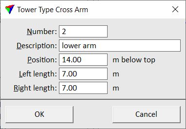
5. Define settings and click OK.
SETTING |
EFFECT |
|---|---|
Number |
Number of the cross arm. Increases automatically for each new arm added to the tower type. |
Description |
Description of the cross arm. |
Position |
Position of the cross arm relative to the top of the tower. |
Left length |
Length of the cross arm to the left side of the tower. |
Right length |
Length of the cross arm to the right side of the tower. |
6. Repeat steps 4 and 5 for all cross arms that belong to this tower type.
7. Select a cross arm and click Add in the Tower Type dialog in order to add an attachment to the selected cross arm.
This opens the Tower Type Attachment dialog:
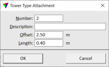
8. Define settings and click OK.
SETTING |
EFFECT |
|---|---|
Number |
Number of the attachment. Increases automatically for each new attachment added to a cross arm. |
Description |
Description of the attachment. |
Offset |
Position of the attachment along the cross arm relative to the tower center. A positive offset creates an attachment right of the tower center, a negative offset left of the tower center. |
Length |
Length of the attachment. |
9. Repeat steps 7 and 8 for all attachments per cross arm and all cross arms of the tower type.
10. Click OK to the Tower type dialog.
11. Close the Settings dialog in order to save the tower type settings for TerraScan.
Tower types are stored in a configuration file TOWER_TYPES.INF in the TerraScan installation folder. You can copy this file to other computers in order to make tower types available on them.