

TerraModeler User Guide
Produce triangles
Not Lite, Not UAV
Produce triangles command creates triangles in an automated process. This is useful for triangle CAD file production on project level, when triangles have to be drawn for a large area.
The automatic triangle production does not rely on surface models loaded in TerraModeler. The ground model can be defined by:
•Laser points in a TerraScan project - usually ground point or model keypoints referenced by a TerraScan project.
•Feature coded breakline elements - in reference CAD files, vector elements created with TerraSurvey or any other application enabled in Triangulate Survey category in the TerraModeler Settings. References are applicable in Bentley CAD only.
•Breakline elements - in reference CAD files, vector elements properly organized by level and symbology or breaklines filtered by rules using the Triangulate Elements tool. References are applicable in Bentley CAD only.
The automatic process writes the triangles as shape elements into multiple CAD files. A seed file is used as starting point for creating the triangle CAD files.
To produce triangle CAD files automatically in a batch process:
1. Prepare the laser data in TerraScan. Normally, this includes the classification of ground or model keypoints. Create a TerraScan project that references the laser point files.
2. If required, create breakline vector elements using CAD and TerraScan tools.
3. Create a seed file for storing the triangles.
The seed file is usually an empty 3D CAD file possibly with a reference file attached. The reference file contains the breaklines that are included in the triangle computation. Alternatively, the breaklines can be stored in the seed file directly.
Reference files are available in Bentley CAD only.
4. If breakline vectors are used, create filtering rules for breaklines using the Triangulate Elements tool.
5. Create shapes that divide the project area into smaller parts.
Each shape results in a separate CAD file for triangles. The shape boundary is used by the software as fence in order to decide whether triangles are inside or outside the shape and to clip the triangles to the shape dimensions.
6. (Optional) Place text elements inside the shapes.
The texts are used for naming the triangle CAD files. If no texts are selected, the files are named by automatic numbering.
7. Select the shapes and (optional) the texts.
8. Select Produce triangles command from the Utility pulldown menu in TerraModeler Surfaces window.
This opens the Produce Triangles dialog:
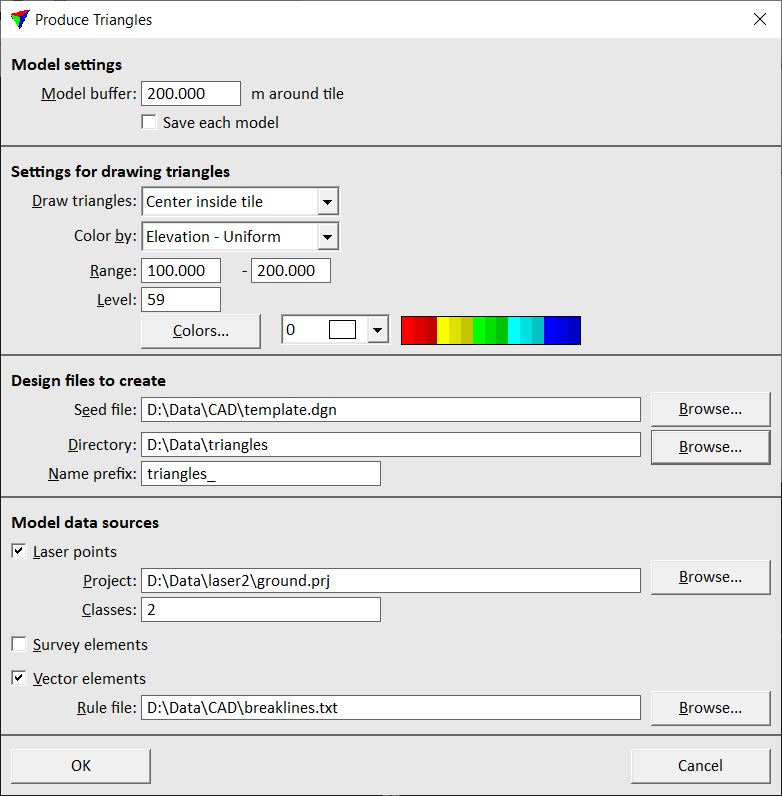
9. Define settings and click OK.
This opens the Triangulate surface dialog. Follow the common steps for Creating a surface model.
The software starts the triangle production. First, it closes the original CAD file from which the process was started. Next, it opens the seed file, computes the triangles for the first shape, writes them into the CAD file, and closes the CAD file. Then the process continues with the next shape. After all triangle CAD file are created, the original CAD file is opened again.
Setting |
Effect |
|---|---|
Model buffer |
Area around each shape for which the surface model is created in addition to the area of the active shape itself. The buffer should be big enough to ensure smooth contour line transitions on shape boundaries. |
Save each model |
If on, a surface model file is saved for each shape. |
Draw triangles |
Defines how triangles are drawn on tile boundaries: •All - all triangles are drawn. •Center inside tile - triangles are drawn completely if the center point is inside the tile. •Clipped to tile boundary - triangles are clipped to the tile boundaries. This results in rectangles along tile boundaries. |
Color by |
Defines the coloring mode: •Elevation - Uniform - triangles are colored by elevation value. The colors are fitted to the given Range of elevation values. •Elevation - Fit to tile - triangles are colored by elevation value. The colors are fitted to elevation values of each tile individually. •Slope - triangles are colored by slope gradient. |
Range |
Elevation range for all triangle CAD files. The range should include all elevation values of the area for which triangles are produced in order to ensure seamless coloring over all triangle CAD files. This is only active if Color by is set to Elevation - Uniform. |
Level |
Level on which the triangles are drawn into the CAD file. |
Colors |
Opens the Color scheme dialog for the definition of a color scheme for triangle coloring. Creating a color scheme of discrete colors for more information. |
Color list |
Opens the Bentley CAD color table for single color selection. |
Seed file |
Location of the CAD file that serves as seed file for triangle production. |
Directory |
Location on a hard disk where the triangle CAD files are stored. |
Name prefix |
Text string that is added at the beginning of the file name of triangle CAD files. If text elements are selected for each shape, the triangle CAD file names are a combination of the prefix and the selected text element. If no text elements are selected, the triangle CAD files are named with the prefix and an automatically increasing number. |
Laser points |
If on, laser points from the given Project and Classes are used as data source. |
Survey elements |
If on, feature coded elements created by TerraSurvey or any other application enabled in Triangulate Survey category in the TerraModeler Settings are used as data source. |
Vector elements |
If on, vector elements filtered as breaklines according to the given Rule file are used as data source. |