

TerraModeler User Guide
Produce lattice models
Not Lite, Not UAV
Produce lattice models command creates lattice model files in an automated process. This is useful for lattice model production on project level, when lattice model files have to be created for a large area.
Lattice models are representations of a surface using a grid structure of points. The lattice model files include regularly distributed points at constant intervals in both, X and Y directions. Common storage formats are text files, image files, or program-specific grid file formats. The automatic process writes the lattice model points into multiple output files of a defined format.
The automatic lattice model production does not rely on surface models loaded in TerraModeler. It is more closely connected with point cloud processing functionality in TerraScan. The source data for the lattice model can be defined by:
•Laser points in a TerraScan project - usually ground points referenced by a TerraScan project.
•Feature coded breakline elements - in reference CAD files, vector elements created with TerraSurvey or any other application enabled in Triangulate Survey category in the TerraModeler Settings. References are applicable in Bentley CAD only.
•Breakline elements - in reference CAD files, vector elements properly organized by level and symbology or breaklines filtered by rules using the Triangulate Elements tool. References are applicable in Bentley CAD only.
To create a lattice model file from a surface model, see Export / Lattice file command.
Workflow for automatic lattice model production:
1. Prepare the laser data in TerraScan. Normally, this includes the classification of ground points. Create a TerraScan project that references the laser point files.
2. If required, create breakline vector elements using CAD and TerraScan tools.
3. If breakline vectors are used, create filtering rules for breaklines using the Triangulate Elements tool.
4. Create shapes that divide the project area into smaller parts.
Each shape results in a separate lattice model file. The shape boundary is used by the software as fence in order to clip the lattice model to the shape dimensions.
5. (Optional) Place text elements inside the shapes.
The texts are used for naming the lattice model files. If no texts are selected, the files are named by automatic numbering.
6. Select the shapes and (optional) the texts.
7. Select Produce lattice models command from the Utility pulldown menu in TerraModeler Surfaces window.
This opens the Produce lattice models dialog:
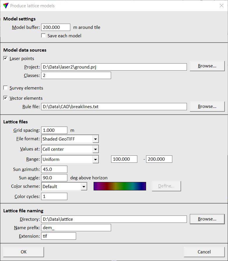
8. Define settings and click OK.
The software starts the lattice model production. It computes the lattice model for the first shape and writes it into the output file. Then the process continues with the next shape until all lattice models are created.
Setting |
Effect |
|---|---|
Model buffer |
Area around each shape for which the surface model is created in addition to the area of the active shape itself. The buffer should be big enough to ensure smooth transitions between lattice models on shape boundaries. |
Save each model |
If on, a surface model file is saved for each shape. |
Laser points |
If on, laser points from the given Project and Classes are used as data source. |
Survey elements |
If on, feature coded elements created by TerraSurvey or any other application enabled in Triangulate Survey category in the TerraModeler Settings are used as data source. |
Vector elements |
If on, vector elements filtered as breaklines according to the given Rule file are used as data source. |
Grid spacing |
Constant distance between points in the grid structure of the lattice model files. |
File format |
Format of the output files. Available formats are: •ArcInfo Grid, Intergraph GRD •GeoTIFF formats, Shaded GeoTIFF •Japanese DMF and LEM •Raw image formats •Surfer ASCII and binary •XYZ text Many of the additional settings for the lattice files depend on the selected format for the output files. |
Values at |
Defines the exact location of the lattice point coordinates: •Cell center - the coordinates of the grid cell center are stored. •Cell corner - the coordinates of the grid cell corner are stored. For some output file formats only one option is available. |
Outside Z |
Defines a constant value for grid cells outside the lattice model area where no elevation value can be derived from the source data. This can be, for example, a software-specific value. |
Z unit |
Defines the elevation value unit for several raster formats. |
Create TFW files |
If on, external georeferencing files are created for GeoTIFFs . |
Write coordinate block |
If on, a coordinate block file is written for Intergraph GRD files. |
Byte order |
Defines the byte order for Raw integer image formats related to the processor type: Intel or Motorola. |
Range |
Determines how the color scheme is fitted to the elevation values for Shaded GeoTIFF files: •Uniform - the range should include all elevation values of the area for which GeoTIFFs are produced in order to ensure seamless coloring over all images. •Fit to tile - the colors are fitted to elevation values of each tile individually. |
Sun azimuth |
Direction of the light for Shaded GeoTIFFs. The direction from the north is defined with zero and angle values increase clockwise. |
Sun angle |
Height of the light source above the horizon. |
Color scheme |
Color scheme to use for Shaded GeoTIFFs: •Default - default color scheme containing magenta, red, yellow, green, cyan, blue, and purple. •Selected colors - use Define button to create a customized color scheme. Define a customized color scheme for more information. |
Color cycles |
Number of color cycles used for Shaded GeoTIFFs. Use zero to create a gray scale display showing triangle slope only. |
Outside points |
Defines for Xyz text files how to handle grid points outside the lattice model area where no elevation value can be derived from the source data: •Skip - outside grid points are not written into the text file. •Output - outside grid points are written into the text file using the constant value given in the Outside Z field. |
Directory |
Location on a hard disk where the lattice model files are stored. |
Name prefix |
Text string that is added at the beginning of the file name of lattice model files. If text elements are selected for each shape, the lattice model file names are a combination of the prefix and the selected text element. If no text elements are selected, the lattice model files are named with the prefix and an automatically increasing number. |
Extension |
Extension for the lattice model files. It is recommended to use the standard extensions for specific file formats, for example, .TIF for GeoTIFFs, .GRD for ArcInfo Grids, .txt, .xyz or .asc for text files. |
Produce lattice models command can be used to create GeoTIFFs of shaded surface model representations in a batch process. Select Shaded GeoTIFF as File format and respective settings for elevation range, sun azimuth, sun angle, and color scheme. The output result is similar to the display created by the Display Shaded Surface tool.