

TerraScan User Guide
Place Tower String
Not Lite
 Place Tower String tool is used to manually digitize a centerline of a powerline. The tool produces a line string element. The tower string must have vertices only at tower locations. The vertices should be located at the center point of a tower as accurate as possible. The tower string can be digitized based on laser data and/or rectified images that show the tower locations.
This tower string is used in later processing steps when detecting wires, validating catenary attachment points, placing towers, and producing reports.
Place Tower String tool integrates line string placement and view panning in one tool which speeds up the digitization process. The tower string is treated as 2D line element by other powerline processing tools. Therefore, the elevation of tower string vertices does not play a role.
In general, any line string or complex line string element can be used as a tower string. If tower positions are provided in a text file, the tower string can be generated automatically by using the Draw as line strings command. In this case, the Place tower string tool is only used to assign a line number to the tower string element.
To prepare for tower string placement:
1. Classify the point cloud in a way that tower locations and wires stand out. This may include steps like
•classify by echo type, classify first of many echoes into a separate class
•classify by centerline using an approximate centerline element of the powerline
•classify ground and above-ground points
It depends on your workflow and project requirements whether the classification is applied to project blocks or only temporarily to loaded points. For placing a tower string, you should load a point cloud that is dense enough for visual tower detection and cover as much as possible from the powerline.
2. Choose a view used as Top view for tower string digitization. Optionally, choose a second view used as Profile view where a profile of the powerline is displayed while digitizing the tower string.
3. Set up the display of laser points in the Display mode dialog. The class(es) with points on towers/wires should be switched on, all other classes off. Set Color by to Elevation.
4. To emphasize the depth perception in the top view, set the Borders setting in the Display mode dialog to a value > 0%. This improves the visibility of towers and wires within their environment. You may also force the software to draw all points on the screen by setting Speed to Normal or Slow.
5. Select CAD file symbology settings to draw the tower string. Set an empty level as active level.
To place a tower string:
1. Select the Place Tower String tool.
This opens the Place Tower String dialog:
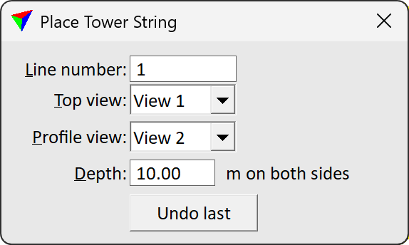
2. Define settings.
SETTING |
EFFECT |
|---|---|
Line number |
Defines a number or name for the tower string. Each tower string should have a unique number in order to clearly identify a powerline. |
Top view |
Number of the view used as top view. This view is primarily used for digitizing the tower string. |
Profile view |
An optional view which displays a profile along the powerline. This is useful to see tower locations more clearly. The profile view can also be used to place vertices for the tower string. |
Depth |
Depth of the profile view. This should include the whole width of a powerline. |
Undo last |
Click on the button in order to delete the last vertex that was placed while digitizing the tower string. |
3. Enter a vertex at the center of the first tower.
This defines the location of the first tower. The dynamic rectangle is displayed whenever the mouse pointer is inside a view. If you place a data click outside the rectangle, the application pans the view in the direction of the click. Placing a data click inside the rectangle adds a new vertex to the tower string.
4. Pan the view to the next tower location.
5. Place a vertex at the center of the tower.
6. Continue with steps 4 and 5 until the last tower of the powerline.
You can click on the Undo last button in order to delete the last vertex that was placed. The undo action can be applied several times.
7. Press the reset button to finish the tower string.
It is recommended to check the tower string for missing or unnecessary vertices. It is essential for automatic wire detection and tower model placement, that the tower string has vertices only at tower locations and that no tower is missing a vertex.
It may happen that a tower string can not be placed along the complete powerline in one operation. In this case, continue placing another tower string that runs in the same direction and starts at the exact end point of the previous tower string. After placing several tower strings along one powerline, join them with the Create Complex Chain tool (Bentley CAD) or Construct Big Element tool (Spatix).
To assign a line number to an existing tower string element:
1. Select the line element that you want to use as tower string.
2. Select the Place Tower String tool.
This opens the Assign Line Number dialog:
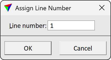
3. Type a number or text string in the Line number field.
4. Click OK.
This assigns the number to the tower string element.