

TerraScan User Guide
Find Powerline Wires
Not Lite
 Find powerline wires tool is used for the automatic detection of powerline wires based on dense point clouds (MLS data) or on point clouds with a consistent pattern of hits from wires (ALS data). In contrast to the Detect Wires tool, this tool does not require alignment element, but on downside may leave gaps to the result if point cloud does not have hits from wires. In contrast to Find Wires tool, this tool searches only wires following catenary shape.
The detection process starts from classified laser points and, optionally, from an alignment element which runs in the direction of the wires. Any overlapping strips in laser point clouds should be matched and overlap should be cut off before running the wire extraction.
Before running the tool, points should be classified into ground and above ground points. One of the above-ground point classes should contain the points on wires (e.g. the high vegetation class) and is then used as source class for the wire detection.
The Find Powerline Wires tool runs on points loaded in TerraScan. It classifies points on wires into a separate class and creates line string elements that are fitted to the points on wires. The software stops each wire at a small distance from its end points. The wire ends can be placed more accurately by using the Check Wire Ends tool.
The tool requires points loaded into TerraScan. However, the same process can be performed for a TerraScan project using the Find wires macro action and then, reading the wire lines from text files using the Read / Wires command.
To detect wires:
1. Load points into TerraScan. Only points on the wires are required.
2. (Optional) Select an alignment element with any Selection tool if you want to detect wires running parallel or perpendicular to the alignment.
3. Select the Find Powerline Wires tool.
This opens the Find Wires dialog:
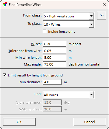
4. Define settings and click OK.
This starts the detection process. The software draws line strings wherever it is able to fit a line to the laser data. The level, color, line weight, and line style of the lines are determined by the active level and symbology settings of the CAD file.
SETTING |
EFFECT |
|---|---|
From class |
Point class that contains points on the wires. Used for fitting the lines. The list contains the active classes in TerraScan. |
|
Opens the Select classes dialog which contains the list of active classes in TerraScan. You can select multiple source classes from the list that are then used in the From class field. |
To class |
Target class into which points on detected wires are classified. |
Inside fence only |
If on, extract wires inside active fence or selected polygon(s) only. |
Wires apart |
Distance threshold for picking neighboring points. Should be larger than point spacing but smaller than distance between parallel wires. |
Tolerance from wire |
Distance around a wire within which the software uses points for fitting the line element. |
Min wire length |
Minimum length of a line element at a wire location. |
Max angle |
Maximum vertical angle off from horizontal of a line element at a wire location. |
Limit result by height from ground |
If on, objects reaching closer than Min distance to the ground are filtered from the result. Use Min distance slightly lower than the actual lowest wire position. |
Find |
Defines what wires the software is searching for: •All wires - wires in all directions. •Parallel to alignment(s) - wires that run parallel to the selected alignment element(s). •Perpendicular to alignment(s) - wires that run perpendicular to the selected alignment element(s). |
Angle tolerance |
Maximum horizontal angular difference between the alignment and a line element at a wire location. This is active only if an alignment element is selected and if Find is set to Parallel to alignment(s) or Perpendicular to alignment(s). |
Within offset |
Maximum horizontal distance between the alignment and a line element at a wire location. This is active only if an alignment element is selected and if Find is set to Parallel to alignment(s) or Perpendicular to alignment(s). |

The vectorization of the wires can be undone by using the Undo command of the CAD platform. The classification of the wires can be undone by using the Undo command of TerraScan.