

TerraScan User Guide
Place Wire String
Not Lite
 Place Wire String tool lets you manually place a line string for a single wire (catenary string) between two towers. You can use this tool in places where the automatic detection of wires fails.
You define the shape of the wire curve with three mouse clicks. Optionally, the start and end point of the line string are defined by mouse clicks as well. Start and end points only effect the length of the wire curve but not its shape.
The line string element for the wire is drawn on the active level using the active symbology settings of the CAD file.
To place a wire string manually:
1. Use Draw Vertical Section tool to create a longitudinal section along the wire from tower to tower.
2. Select the Place Wire String tool.
This opens the Place Wire String dialog:
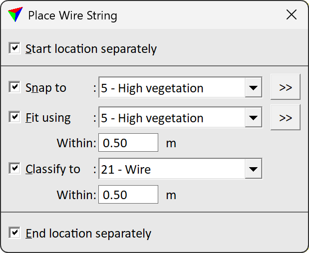
3. Define settings.
SETTING |
EFFECT |
|---|---|
Start location separately |
If on, the first data click defines the start point of the catenary string. |
Snap to |
If on, the three curvature points are snapped to the closest laser points in a given class. This lock is normally on. |
|
Opens the Select classes dialog which contains the list of active classes in TerraScan. You can select multiple source classes from the list that are then used in the Snap to field. |
Fit using |
If on, the wire string is fitted to laser points in the given class within the given tolerance. |
|
Opens the Select classes dialog which contains the list of active classes in TerraScan. You can select multiple source classes from the list that are then used in the Fit using field. |
Classify to |
If on, laser points within the given radius around the wire string are classified into the given class. |
End location separately |
If on, the last data click defines the end location of the wire string. |

4. (Optional) Define the start point of the wire string with a data click.
5. Define the first, second, and third curvature point with data clicks.
6. (Optional) Define the end point of the wire string with a data click.
The application draws the wire string defined by the given points temporarily into the CAD file.
7. Accept the wire string with another data click.
The wire string is drawn permanently into the CAD file and laser points are classified into the given target class, if the corresponding setting is switched on.
The placement of a wire string can be undone by using the Undo command of the CAD platform. The classification of the points along the wire string can be undone by using the Undo command of TerraScan.