

TerraScan User Guide
Waveform Processing
Not Lite, Not UAV
TerraScan is able to read waveform information from LAS 1.3 and 1.4 files, WDP files (external waveform data storage for LAS files) and from TopEye.TEW 1.15 (MarkII) files. It uses the waveform information for processing tasks. It is not possible to write out files that include waveform information.
TerraScan UAV does not include any waveform capabilities.
Waveform capabilities
If waveform data is available, you can perform the following processing steps:
•View Waveform for a point in a graph and export waveform information of a point into a text file.
•Extract echo properties for laser points:
▪Echo length - relative length (millimeter) of a return signal compared to a typical return from a hard surface.
▪Echo normality - difference in shape of a return signal compared to a typical return from a hard surface.
▪Echo position - difference in position of a peak of a return signal compared to a typical return from a hard surface.
•Classify laser points By echo length.
•Extract Echoes in problem areas using a specific echo extraction logic:
▪Last possible - for example in areas with dense low vegetation where the default extraction logic did not provide ground points.
▪All possible or All distinct - for example in places where points on some feature are missing, such as powerline wires.
▪First possible.
Waveform processing principles
In a TerraScan project, the block binary files must be saved as LAS or FastBinary files in order to enable the use of waveform data for processing. Waveform-related attributes, such as echo length, echo normality, and echo position can only be stored in FastBinary format.
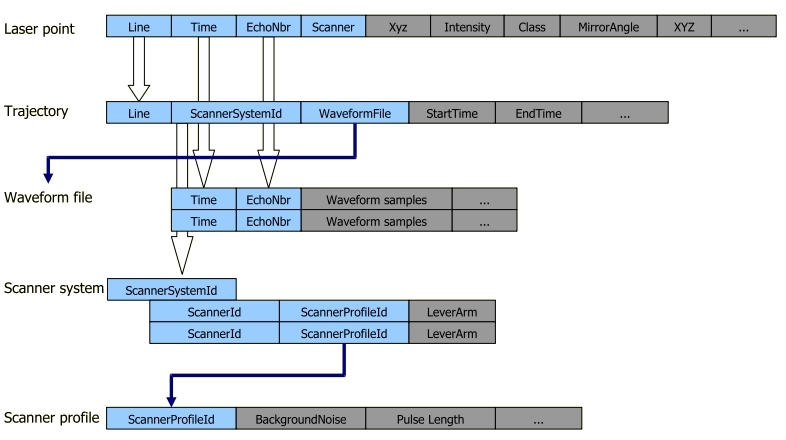
The waveform files are linked to laser points via the trajectory files. The Trajectory information dialog contains an input field Waveform which defines the file(s) used for reading waveform information. Once a laser point is assigned to a trajectory (by the line number) and the trajectory is linked to a waveform file, the software is able to find the waveform information for any laser point using the time stamp and the echo number stored for the laser point.
For the extraction of echo properties and of additional points, the software also needs a scanner waveform profile. The profile stores properties of typical returns from a single hard surface. These properties include:
•the background noise level
•the pulse length at 50% of peak strength
•the pulse length at 35% of peak strength
•the shape of the return pulse
•the system-derived point position relative to the return pulse
The scanner waveform profile can be extracted from laser point samples on hard, flat, open ground surfaces. There should be only-echo returns and some intensity variation within the sample area. The sample areas must not be located at the edges of scan lines. The scanner waveform profile is then automatically computed from the sample laser points.
Finally, the scanner waveform profile must be referenced by a scanner system definition which in turn must be linked to the trajectory files.
The following figure illustrates the method how TerraScan finds waveform information for a laser point.
TerraScan expects waveform data stored as 16-bit unsigned integer values. Some software for generating waveform data uses signed integer values which leads to problems when TerraScan reads the waveform data. Depending on the software information provided in the header of an LAS file, TerraScan excludes values > 32767 in order to avoid errors caused by signed integer values in the waveform files.
1. Load trajectories into TerraScan using the Manage Trajectories tool.
2. Link trajectories with waveform files using the Edit information or Link to waveform files commands of the Trajectories dialog.
3. Create a TerraScan project using the Define Project tool, storage format must be FastBinary for storing echo properties, or LAS.
4. Import points into the project using the Import points into project command of the Project dialog, deduce line numbers from trajectories.
This enables the display of waveform information using the View Waveform tool.
5. Draw polygons around sample areas of single, open, hard surfaces that contain only-echo returns and some variation in intensity values. Sample areas should not be too close to scan corridor edges.
6. Classify points inside the polygons into a separate class using Inside fence command or By polygons classification routine.
7. Create a scanner waveform profile using the user controls in Scanner waveform profiles category of TerraScan Settings.
You have to repeat steps 5 to 7 for all scanners or lines collected with different pulse rates.
8. Link the scanner waveform profiles with scanner system definitions using the user controls in Scanner systems category of TerraScan Settings.
9. Link the trajectories with scanner system definitions using the Edit information command of the Trajectories dialog.
This enables the extraction of echo properties using the Extract echo properties command of the Project dialog or the Extract echo properties command for loaded points, and the extraction of additional points using the Extract Echoes tool.