

TerraScan User Guide
Travel Path
 Travel Path tool lets you view an animation along an alignment element. The tool provides an excellent way for traversing along the survey path and checking the data visually. The tool can also save the frames as pictures on hard drive for project documentation.
The alignment element can be any linear element. In most cases you create the element manually or draw, for example, a trajectory line into the CAD file by using the Draw into design command. Alternatively, you can use TerraScan’s Draw from points command which draws an approximate flight path deduced from the order of loaded laser points.
You can define what kind of views you want to see while traveling along the alignment. Supported view types include top, cross section, longitudinal section, isometric and camera views.
To create an animation along an alignment:
1. Draw and select the alignment element.
2. Select the Travel Path tool.
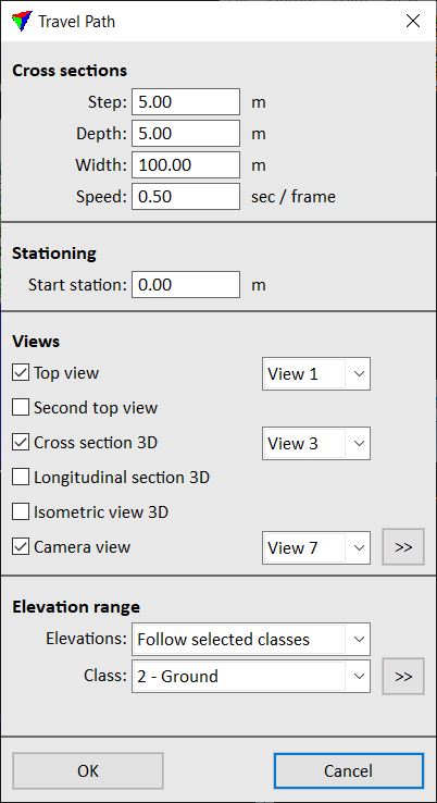
This opens the Travel Path dialog:
3. Define settings and click OK.
The application constructs internal tables for the animation and then opens the Travel Player dialog:

SETTING |
EFFECT |
|---|---|
Step |
Step along alignment between consecutive cross sections. |
Depth |
Full depth of each cross section. Each cross section covers a rectangular area defined by the Depth and Width values. |
Width |
Full width of each cross section. Each cross section covers a rectangular area defined by the Depth and Width values. |
Speed |
Speed for automatic animation display. |
Start station |
Defines the point on the alignment element from which the animation starts. |
Views |
CAD file views that are used for displaying the animation: •Top view - displays data from the top. •Second top view - displays data from the top. •Cross section 3D - displays data in a cross section. •Longitudinal section 3D - displays data in a longitudinal section. •Isometric view 3D - displays data in an isometric view. •Camera - display data in a camera view. Click on the >> button in order to open the Travel Path Camera Settings dialog and define settings for the camera view. |
Elevations |
Method of elevation range computation which defines how the animation follows elevation changes in the data: •Follow all points - all points determine the visible elevation range. •Follow selected classes - points from selected classes determine the visible elevation range. Select a single class from the Class list. Click on the >> button in order to open the list of active classes and select several classes. •Follow 3D alignment - the alignment element determines the center elevation and the visible elevation range is determined by the Minimum dz and Maximum dz values given relative to the alignment element. •Fixed - a fixed elevation range defined by Minimum z and Maximum z values is used for the whole animation. |
The Travel Player dialog contains the following commands and tools for traveling along the alignment element:
MENU/TOOL |
COMMAND/TOOL NAME |
EFFECT |
|---|---|---|
File |
Store travel path frames as picture files. |
|
Move |
Using mouse |
Update a cross section view dynamically as you move the mouse pointer along the alignment. If you place a data click, the tool updates all views. |
Move |
To start |
Move to the start of the alignment and update all views. |
Move |
To end |
Move to the end of the alignment and update all views. |
|
Play backward |
Start automatic animation display backward along the alignment. |
|
Step backward |
Move stepwise backward along the alignment. |
|
Stop |
Stop automatic animation display. |
|
Step forward |
Move stepwise forward along the alignment. |
|
Play forward |
Start automatic animation display forward along the alignment. |


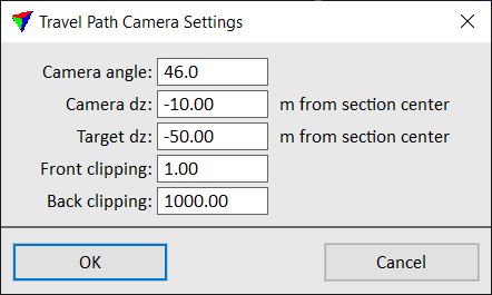
The Travel Path Camera Settings dialog lets you define settings for a camera view.
SETTING |
EFFECT |
|---|---|
Camera angle |
Field-of-view angle of the camera. |
Camera dz |
Altitude of the camera position. Defined as elevation difference from the section center (= alignment element). |
Target dz |
Altitude of the target position. Defined as elevation difference from the section center (= alignment element). |
Front clipping |
Distance up to which the content of the view is clipped in the foreground. Data is displayed in the range between Front and Back clipping. |
Back clipping |
Distance after which the content of the view is clipped in the background. Data is displayed in the range between Front and Back clipping. |
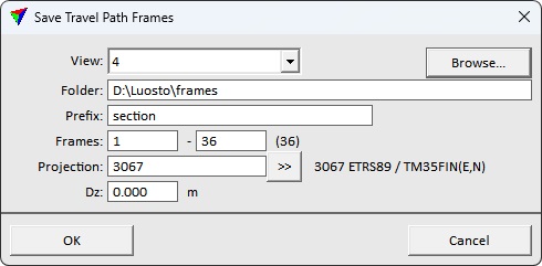
The Save Travel Path Frames dialog lets you save travel path views as TIFF files. This functionality suitable for project reporting. Similar, but more advanced and specifically designed for flythru animation production available in TerraPhoto Flythru movies.
SETTING |
EFFECT |
|---|---|
View |
CAD view to save. Use a view set to update in Travel path setup. |
Folder |
Directory on a hard disk where frames are saved. |
Prefix |
Text that is added in the beginning of the frame file names. The frame number is automatically added to the file name. |
Frames |
Frame range to save. |
Projection |
Projection system of the loaded data. Projection system is required to store the location tag correctly to the TIFF files. |
Dz |
Elevation shift to apply to the position tag of each frame. Useful for shifting frames to avoid overlap with other data when results are exported for visualization on an interactive map. |