

TerraScan User Guide
Travel View
 Travel View tool lets you setup perspective views by defining a viewer position, viewer height above a reference surface, and vertical viewing angle. Further, the tool provides user controls for navigating in the perspective view.
To setup and travel in a perspective view:
1. Open and setup a CAD file view that you want to use as perspective view.
The setup may include display settings for the point cloud, vector data and imagery, if available.
2. Select the Travel View tool.
This opens the Travel View dialog:
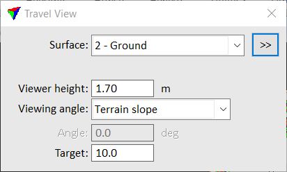
3. Define settings.
SETTING |
EFFECT |
|---|---|
Surface |
Point class that defines the reference surface for the viewer. Used as the base elevation level for calculating the viewer position. Alternatively, select Fixed elevation and define the viewer's base point elevation in the Base Z field. |
|
Opens the Select Classes dialog which contains the list of active classes in TerraScan. You can select multiple source classes from the list that are then used in the Surface field. |
Base Z |
Reference elevation for computing the viewer position. This is active only if Surface is set to Fixed elevation. |
Viewer height |
Height of the viewer above the reference elevation. |
Viewing angle |
Defines the vertical viewing angle: •Horizontal - the viewer looks horizontally forward. •Terrain slope - the viewer looks according to the terrain slope in view direction. •Angle down - the viewer looks down by the given Angle. •Angle up - the viewer looks up by the given Angle. |
Target |
Maximum distance to define a target position. |

4. Define the viewer position by placing a data click inside a CAD file top view.
This displays the viewer position and the viewing angle dynamically if the mouse pointer is moved.
5. Define the target position by placing another data click inside the CAD file top view.
6. Select another CAD file view as target view.
This displays the point cloud in the target view which is changed into a perspective view. The software opens the Travel View dialog for navigating in the perspective view:
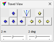
Move the viewer forward/backward, left/right by using the blue arrow buttons on the left side of the dialog. Adjust the moving distance per button click with the slider on the left side. The distance can be adjusted to fixed values between 0.1 and 100 meters.
Turn the viewing direction up/down, left/right by using the yellow arrow buttons on the right side of the dialog. Adjust the turning angle per button click with the slider on the right side. The angle can be adjusted to fixed values between 0.5 and 90 degree.
Define a new perspective view by activating the perspective view tool again pressing the button in the middle. It is not necessary to activate perspective view tool again every time defining a new view, but only when the tool was deactivated in between. The tool is deactivated when some other tool is activated.
After at least one data click on the buttons of the Travel View dialog, you can also use the <Arrow-up> and <Arrow-down> keys to move forward/backward, and the <Arrow-left> and <Arrow-right> keys to turn the viewing direction to the left/right.
The other Travel View dialog is still available and settings can be adjusted. The new settings are applied when the next navigation step is done. Even if the Travel View dialogs are closed, the tool is still active and you can setup new perspective views by starting from step 4.
Define field of view and view clipping options for this tool in Travel View tool settings.