

TerraScan User Guide
Find Poles
Limited in Spatix
 Find Poles tool is used for the automatic detection of pole objects based on point clouds. This makes sense if you need to detect and possibly vectorize a large amount of identical poles or other objects from a point cloud. It requires a few preparation steps, such as pre-classification of the point cloud and the definition of a sample object for each pole type to detect. Therefore, it is probably not the fastest solution for detecting and vectorizing just a few poles.
The steps for defining a sample object are described in the Pole library category of TerraScan Settings.
Any overlapping strips in the laser data must be matched and overlap should be cut off before running the object detection. It is required to do a classification of the point cloud in order to separate points on potential objects from other points. This includes ground classification, computation of distance from ground, and above-ground classification by distance. Furthermore, it is required to assign groups in order to detect objects.
The object detection can be supported by an alignment element. A trajectory line drawn in the CAD file can be used as alignment. The object definition defines whether an object is located left or right of the alignment or, with other words, whether the scanner system was driven on the left side or right side of the object. It is recommended to use an alignment in order to speed up object detection significantly. In addition, the alignment element can be used to classify point groups by centerline. This classifies potential objects within an offset from the alignment into a separate class and thus, reduces the amount of data for the object detection.
In the object detection process, the software compares point groups in the project data set to point groups in the pole library by testing different 3D rotations. If a match is found, it classifies the point group into the target class specified in the object definition. In addition, it can place cell elements in the CAD file. An example workflow for creating a cell element is provided in Pole library category of TerraScan Settings. Cells are stored in cell libraries. A cell library must be attached to the CAD file before cells from the library can be used. The tool creates a copy of the orginal cell element for each detected object. The cell is shifted to the correct object location and rotated according to the object rotation. The cell is further clipped at ground elevation, if the corresponding setting for the object item is switched on. The extent of the cell is not adjusted to the point cloud. If no cell library is attached or if the cell for an object is not available, the process only classifies points.
The tool is most confident in detecting poles along roads or rail tracks that have been driven during the data collection. All scanners of a system should see a pole from the same side. Thus, most of the points are on the sides of the pole facing towards the road. Poles on side roads/rail tracks or on bridges away from the data collection path are not detected automatically.
The tool requires laser points loaded into TerraScan. However, the same process can be performed for a TerraScan project using the Find poles macro action and then, reading the pole cells from text files using the Read / Poles command.
To detect poles automatically:
1.Load points into TerraScan.
2.Select Scan Settings tool and open Pole library category.
3.Click inside the rectangle field next to an object item in order to activate/deactivate object items for detection. Activate object items to detect in the point cloud. Deactivate all other object items.
4.Close the TerraScan settings dialog.
5.Draw a vertical section in one of the CAD file views.
6.(Optional, to place cells for poles) Open the Cell Library window of Bentley CAD and attach the cell library that contains the cell element(s) for the objects in the point cloud. (Not Spatix)
7.(Optional, but highly recommended) Select the alignment element.
8.Select Find Poles tool.
This opens the Find Poles dialog:
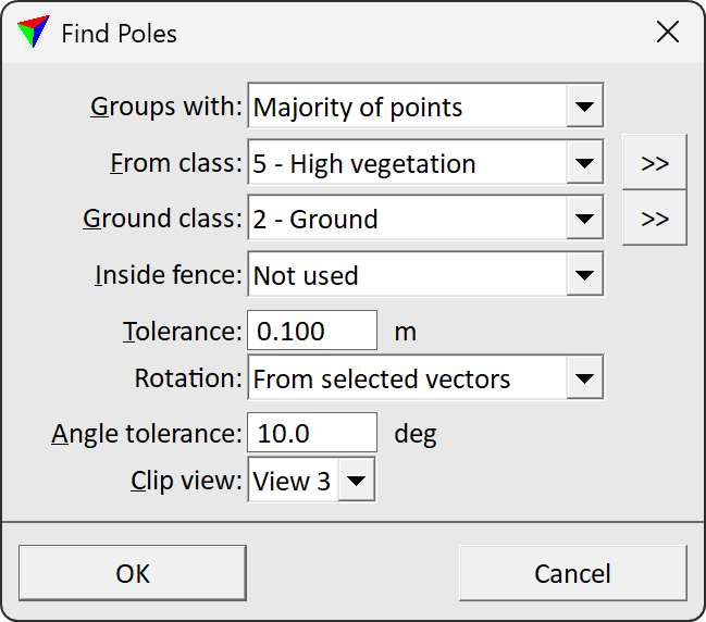
9.Define settings and click OK.
This starts the detection process. The software classifies point groups into the target class specified in the object definition and (optionally) places cell elements in the CAD file. The cells are only placed if a cell library is attached to the CAD file and if a cell with the name specified in the object definition is available. The cell is placed on the active level in the CAD file.
SETTING |
EFFECT |
|---|---|
Groups with |
Determines which groups are used for detection: •One or more points - groups with one or more points in the source class. •Majority of points - groups with more than 50 % of points in the source class. •All points - groups with all points in the source class. |
From class |
Point class that contains points on static parts of objects. These points of a group are compared to the sample object in the pole library. |
|
Opens the Select classes dialog which contains the list of active classes in TerraScan. You can select multiple source classes from the list that are then used in the From class field. |
Ground class |
Point class that represents the ground. Used for clipping a cell at ground elevation in the Clip view. |
|
Opens the Select classes dialog which contains the list of active classes in TerraScan. You can select multiple source classes from the list that are then used in the Ground class field. |
Inside fence |
Determines how a fence or selected polygon(s) effect the classification: •Not used - fence or selected polygons are ignored. •One or more points - groups are classified if one or more points are inside. •Average xy - groups are classified if the average xy point is inside. •Majority of points - groups are classified if more than 50 % of points are inside. •All points - groups are classified if all points are inside. |
Tolerance |
Maximum distance between a point in the sample object and a point from the object to be detected in a project point cloud. The elevation tolerance is further determined by multiplying this value with the At center and At edge factors given in the object item definition. For dense MLS point clouds, 0.1 m is the recommended setting. A smaller value may improve the result but slow down the process significantly. A larger value should be used for point clouds with a lower density. For low-altitude dense ALS point clouds of powerlines, 0.25 m may be a good estimate for detecting powerline towers. The larger the value, the higher the probability that objects are detected even though the point group differs from the sample object group. |
Rotation |
Horizontal rotation of an object relative to the alignment: •Free - any rotation of the object is possible. This slows down the detection process significantly. •From selected vectors - the object is rotated only within the given Angle tolerance relative to the alignment. This is active only if an alignment element has been selected before the tool was started. |
Angle tolerance |
Maximum allowed angular difference between an object and the alignment. The larger the angle, the slower the process. Use a smaller value (e.g. around 3.0 deg) for objects that have the same rotation angle relative to the alignment, such as towers along a straight powerline. This is active only if Rotation is set to From selected vectors. |
Clip view |
CAD file view used for applying a clip mask to the object's cell element. The view must be a vertical section view. If Clip to ground setting is switched on for an object in the object item definition, the cell elements are clipped at the elevation of the Ground class. |

You can undo the placement of cell elements for objects by using the Undo command of the CAD platform. You can undo the classification of points for objects by using the undo command of TerraScan.
At the moment, cells and thus, the cell placement capability of the Find Poles tool does only work in Bentley CAD. There is not yet any corresponding element type in Spatix.