

TerraScan User Guide
Pole library
Pole library category shows a list of object definitions that can be used for automatic object detection. Currently, poles are the objects that can be detected automatically from very dense point clouds, such as mobile scanning point clouds. Find poles tool makes use of the pole library.
Object detection in TerraScan relies on the computation of distance from ground and groups of points with a certain shape. Therefore, it is required to compute distance and assign groups in a point cloud in order to define an object in the Settings and to detect objects. For object definition, it is further required to classify the static parts of a sample object in order to separate them from the variable parts of the object. Distance computation, group assignment, and classification can be done using the menu commands for loaded points in the TerraScan window, manual classification tools, or macro actions.
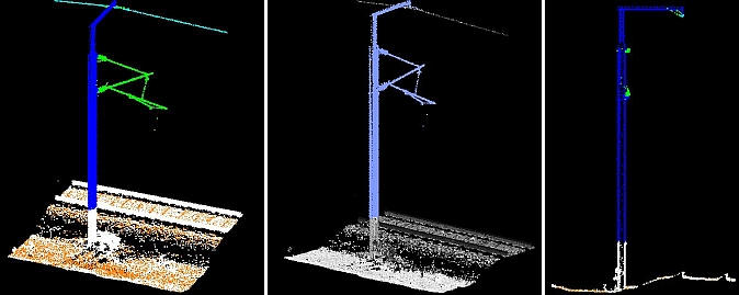
Sample point cloud for object definition. Classification of static (blue)/variable parts (green) shown on the left and group shown in the center image.
The right image shows a vertical cross section of the sample point cloud for object definition. The arm of the pole points in the direction of the alignment, such as the trajectory line.
The object detection can be supported by an alignment element, a line element drawn in the CAD file. A trajectory line drawn in the CAD file can be used as alignment. The object definition defines whether an object is located left or right of the alignment or, with other words, whether the scanner system was driven on the left side or right side of the object. It is recommended to use an alignment in order to speed up object detection significantly.
In the object detection process, the software classifies points on objects into a given class. The object definition determines the target class.
(Bentley CAD only) In addition, it may place cell elements in the CAD file. A cell element can be created using Bentley CAD tools for cell management. Cells are stored in cell libraries. A cell library must be attached to the CAD file before cells from the library can be used. The object definition determines the name of the cell that is placed for a certain object type.
The pole items of the library are stored in text files in the TerraScan installation folder, for example C:\Terra64\Tscan\OBJECT_LIBRARY. The text file stores the points belonging to the group in the sample point cloud using object coordinates. The origin of the pole group is defined by the base point of a pole object and set to XYZ = 0,0,0 in the object coordinate system. The X axis points in cross section direction of the pole object (to the right in a cross section view), the Y axis is perpendicular to the X axis (away from the viewer in a cross section view), and the Z axis points upwards (up in a cross section view).
You can Add, Edit, and Delete pole objects by using the corresponding buttons in the Settings dialog. The delete action deletes the pole definition from the settings but it does not delete the object text file from the object library folder.
To add a new pole definition to the library:
1. Open the Pole library category
2. Choose a sample pole in the point cloud. You may create a separate file from the sample.
3. (Optional) Make sure that the sample represents an "ideal" pole, for example, a vertical pole. You may rotate the sample point cloud of a leaning pole by using the Rotate points button in the Settings dialog.
4. (Optional) Create a cell element by using Bentley CAD tools for cell management. (Not Spatix)
If distance computation and grouping is not yet done for the point cloud, it must be done for the sample before an pole can be defined.
5. Draw an accurate vertical cross section of the sample pole. If the pole has a horizontal cross arm, the centerline of the section should follow the direction of the cross arm accurately.
6. Click Add in the Settings dialog.
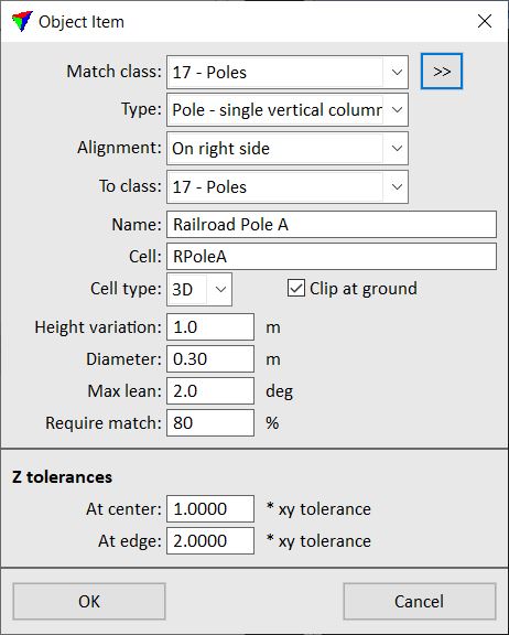
The Pole Item dialog opens:
7. Define settings and click OK.
8. Define the pole base point with a data click in the cross section view.
The base point defines the origin of the pole object in the object coordinate system. You may snap to a point at ground level in order to define the base point.
9. Define the group which defines the pole with another data click close to points of the group.
This adds the pole definition to the library.
10. Close the Settings dialog in order to save the pole library settings for TerraScan.
SETTING |
EFFECT |
|---|---|
Match class |
Point class used for defining the sample pole. The class should contain point from the static parts of an object. This is only available when a new pole is added. The setting is not available when an existing pole definition is edited. |
Type |
Type of the object: •Pole - single vertical column - pole object with a single column and maybe horizontal parts. •Pole - complex - pole object of a more complex structure. |
Alignment |
Location of a pole object relative to an alignment element: •Not defined - no location relative to an alignment is defined. •On left side - the alignment is located left of the sample object. •On right side - the alignment is located right of the sample object. |
To class |
Point class into which points of groups of this pole type are classified. |
Name |
Name of the pole item. Defines the name of the text file created for this pole definition. |
Cell |
Name of the cell element that is placed for the pole item. The same name must be used for the cell element in a Bentley cell library. This is optional, if not defined, cell models are not created during pole extraction. |
Clip at ground |
If on, the cell element is clipped at ground level. Parts under ground are removed from the cell element. |
Height variation |
Maximum variation of the height of the pole. |
Diameter |
Approximate diameter of the pole column. This is only available if Type is set to Pole - single vertical column. |
Max lean |
Maximum angle by which a pole may be off from vertical. |
Require match |
Determines how well an object must match the sample pole definition in order to be detected as this pole type. |
At center |
The two Z tolerances values determine the elevation variation of points on vertical parts relative to horizontal parts of an object in the point cloud compared to the sample object point cloud. In very dense MLS point clouds, points on the edge of objects, such as vertical arms of street lamps, railway posts, etc. vary more than points on the central vertical part of the object. Thus, At edge value should be larger than At center value, for example 1.0 vs. 3.0. In less dense ALS point clouds, horizontal parts of objects, such as powerline tower arms, are represented more confidently and with less variation than vertical parts. Thus, At center value should be larger than At edge value, for example 3.0 vs. 2.0. |
At edge |
Object definitions are stored in a configuration file OBJECT_LIBRARY.INF in the TerraScan installation folder. The sample objects in the library are stored in folder \OBJECT_LIBRARY as text files with the extension .XYZ. You can copy these files to other computers in order to make pole definitions available on them.
Rotate points can be used to rotate a sample point cloud in a section view. This may be required, for example, to get a sample pole object vertical.
To rotate points:
1. Draw a vertical cross section of the object. The vertical part of the object should be clearly visible in the section. If the object has a horizontal cross arm, the centerline of the section should follow the direction of the arm accurately.
2. Select Rotate points button in the Pole library category of the Settings.
3. Define a first base point with a data click, for example close to the lower end and on the left side of a pole.
The software shows a horizontal line at the mouse pointer location which acts as a helping line for defining the base of a vertical object.
4. Define a second base point with another data click on the right side of a pole.
The software shows a vertical helping line which extends dynamically with the mouse pointer movement.
5. Define a first top point with a data click, for example close to the upper end and on the left side of a pole.
The software shows a horizontal line at the mouse pointer location which acts as a helping line for defining the top of a vertical object.
6. Define a second top point with another data click on the right side of a pole.
This rotates the point cloud according to the four points defined with data clicks.
7. Use the Cut section tool in order to create another vertical section of the pole that is perpendicular to the previous section.
8. Repeat steps 2 to 6 in order to rotate the pole in the second section view.
Not Spatix
A Bentley cell element can be placed by TerraScan for representing a pole. The cell may be a simple 2D symbol or a more complex 3D structure. The cell origin should be the same as the origin/base point of the TerraScan object group. For objects standing on the ground, the origin should be on the ground.
Bentley cell elements are stored in cell libraries. A cell library is stored in files with the extension .CEL. In order to create, modify, or use a cell element, the cell library must be attached to the CAD file.
Example workflow for creating a cell element:
1. Draw a vertical cross section of the object. If the object has a horizontal cross arm, the centerline of the section should follow the direction of the arm accurately.
A line element drawn in the center of the cross arm and following its direction may be used as helping line for creating accurate cross section views and for making the section view creation repeatable.
2. (Optional) Draw another helping line that starts from the center base point of the object. For a single-column pole, the base point is the center of the column at ground elevation. Use, for example, Mouse point adjustment tool in order to place the helping line start point exactly at ground elevation.
3. Digitize the object using Bentley CAD tools. The object may be represented by lines, shapes, or any other element type. Several elements of different types may form a cell. Snap to the start point of the helping line created in step 2 in order to place the base point of the cell on the ground. You may use any drawing aids of Bentley CAD for digitizing the elements of the cell.
4. Extend the base point of the object below the ground. For example, if the height of an object may vary by around 1.5 m, extend the base point to about 2 m below ground. You may use, for example, the Extend Line tool of Bentley CAD in order to extend a line element to a specified distance below ground.
5. Select Define Cell Origin tool of Bentley CAD. Snap to the start point of the helping line created in step 2 and place the origin of the cell with a data click. The cell origin should be located on the base point of the object at ground elevation.
6. Select all elements that form the cell for the object.
OR
6. Select Place Fence tool of Bentley CAD. Set Fence Type to be Block or Shape, and Fence Mode to be Inside. Place a fence that includes completely all elements that form the cell for the object. Do not include the helping lines.
7. Open the Cell Library window of Bentley CAD.
8. Select New command from the File pulldown menu in order to create a new cell library. Define a location and name for storing the library.
OR
8. Select Attach file command from the File pulldown menu in order to attach an existing cell library. Browse to the storage location and select the library file.
9. Select the Create button from the Cell Library window. The button is only active if a cell origin has been placed and if elements are selected or inside a fence (steps 5 and 6).
10. Define a name and description of the cell. The cell name is the link between the TerraScan pole item and the cell element. Select cell type Graphic and click Create.