

TerraScan User Guide
Find Rails
 Find rails tool is used for the automatic vectorization of rails. In ALS data, the method requires the classification of the points on top of the rails. Then, the tool tries to find parallel linear structures in the point cloud with a given distance (track width). In very dense MLS data, the method is based on a track cross section definition. The tool looks at consecutive cross sections of laser data along an alignment element. For each cross section, it tries to find the position where a user-defined cross section profile of the track matches the best number of laser points.
The vectorization process starts from an alignment element which represents the approximate direction (ALS) or centerline (MLS) of a rail track. Any digitized line element can be used as alignment. You can use, for example, Draw into design command for trajectories and apply a lever arm correction in order to derive a centerline from the trajectory. The lever arms are the three components of the vector between the IMU and the center of the rail track.
Alternatively, for MLS data the trajectories can be used directly for the rail detection. They must be imported with the correct system definition values for IMU misalignment. See Scanner systems category of TerraScan Settings for more information. In addition, they must be projected on the ground and to the center of the rail track. This can be established by applying a lever arm correction to the original trajectories by using the Add lever arm command. In the vectorization process based on trajectories, the software uses the roll angle of the trajectory positions as cant (superelevation) angle of the rail track.
For MLS data, the tool further requires a cross section profile defined in TerraScan Settings. The profile includes the two rails of a track, possibly places where there are no laser point (shadow parts of rails), and the location of lines that the software creates in the vectorization process. The creation of a rail track cross section is described in Rail section templates category of TerraScan Settings.
Any overlapping strips in the laser data should be matched and overlap should be cut off before running the rail vectorization. The By centerline classification routine should be used for an approximate classification of the points in the track area (ALS) or on rails (MLS). You can use, for example, the alignment element drawn in the CAD file for the classification by centerline.
The Find Rails tool runs on points loaded into TerraScan. It creates line string elements at the location(s) defined in the cross section profile. Rail lines detected from ALS data contain a huge number of very dense vertices. The location of close-by vertices may vary at very short distances. It is recommended to apply smoothing to the line elements in order to remove locational variation. In addition, thinning should be applied in order to remove unnecessary vertex density along the smoothed line elements.
To vectorize rails automatically:
1.Load points into TerraScan. Only points within the track area (ALS) or on and close to the rails (MLS) are required.
2.(Obligatory for MLS, recommended for ALS) Select the alignment element with the Selection tool of your CAD platform.
OR
2.(MLS only) Load trajectories into TerraScan using the Manage Trajectories tool.
3.Select Find Rails tool.
This opens the Find Rails dialog:
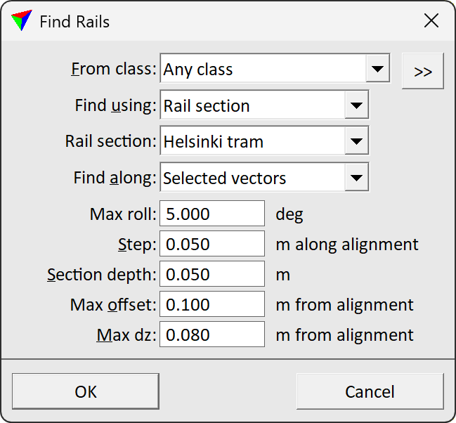
4.Define settings and click OK.
This starts the vectorization process. The level, color, line weight, and line style of the lines are determined by the active level and symbology settings of the CAD file.
Depending on the amount of laser data, the accuracy of the alignment element, and how well the software can fit the rail track cross section to MLS data, the process may take some time. It is recommended to test the settings for the tool with small data samples.
SETTING |
EFFECT |
|---|---|
From class |
Point class that contains points on and close to the rails or within the track area. Used for fitting the rail lines. The list contains the active classes in TerraScan. |
|
Opens the Select classes dialog which contains the list of active classes in TerraScan. You can select multiple source classes from the list that are then used in the From class field. |
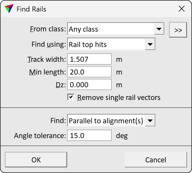
Find using |
Method how rails are detected: •Rail section - based on a cross section definition of the track. This is recommended for very dense point clouds, such as MLS data, where the rail profile is visible. •Rail top hits - based on pre-classified points on rail heads. This can be used with sparse point clouds, such as ALS data, where the rail profile is not visible. |
Rail section |
Name of the rail track cross section. The list contains all sections that are defined in Rail section templates category of TerraScan Settings. This is active only if Find using is set to Rail section. |
Find along |
Defines the alignment element used for the vectorization: •Trajectories - active trajectories in TerraScan. •Selected vectors - a selected line string element. This is active only if Find using is set to Rail section. |
Trajectories |
Trajectory numbers that are used for the vectorization. Separate several numbers by comma. Type 0-65535 for using all trajectories. This is active only if Find along is set to Trajectories. |
Max roll |
Maximum value of the cant angle (= rail track superelevation). This is active only if Find along is set to Selected vectors. This is active only if Find using is set to Rail section. |
Step |
Distance between locations along the alignment where the software tries to fit the rail track cross section to the loaded points. This is active only if Find using is set to Rail section. |
Section depth |
Depth of a section in the point cloud data where the software fits the rail track cross section to the laser points. This is active only if Find using is set to Rail section. |
Max offset |
Maximum horizontal distance between the alignment and a line element that the software should draw as result of the vectorization process (usually a line on the rails or the track centerline). This is active only if Find using is set to Rail section. |
Max dz |
Maximum vertical distance between the alignment and a line element that the software should draw as result of the vectorization process (usually a line on the rails or the track centerline). This is active only if Find using is set to Rail section. |
Track width |
Distance between the two parallel rails of a track. This is active only if Find using is set to Rail top hits. |
Min length |
Minimum length of a line element that is drawn for a rail. This is active only if Find using is set to Rail top hits. |
Dz |
Elevation correction that is applied to detected rail lines. This may correct a systematic elevation bias due to noise or mismatch in the data. This is active only if Find using is set to Rail top hits. |
Remove single rail vectors |
If on, lines are removed if there is no corresponding parallel line within the track width. This is active only if Find using is set to Rail top hits. |
Find |
Determines how rails are detected relative to selected alignment element(s): •All rails - all potential rail lines are drawn independently of the direction. •Parallel to alignment(s) - only rail lines with a direction within the given Angle tolerance to the alignment element are drawn. This is active only if Find using is set to Rail top hits. |

You can undo the vectorization of rails by using the Undo command of the CAD platform.