

TerraScan User Guide
Check Building Models
 Check Building Models tool can be used to check automatically created building models in an organized way. It is intended to be used after building vectorization by Vectorize Buildings tool, Vectorize Buildings macro action, or Create Buildings from Polygons tool. The tool includes a validation option for checking the planarity of roof planes and/or the match between vector models and building footprint polygons.
The Check Building Models dialog shows a list that contains building models in the CAD file that are drawn on the levels defined in Building vectorization / Levels category of TerraScan Settings. If a line in the list is selected, the software updates the display in a number of CAD file views as defined in the tool settings. The tool can update different view types, such as top, isometric, section, and camera views which may show the building models within a point cloud and/or on top of images.
With the help of the list, you can start to work with tools of the Building Patches toolbox and the Building Edges toolbox in order to improve the accuracy of the building models.
To check building models:
1. Select Check Building Models tool.
This opens the Check Building Models dialog:
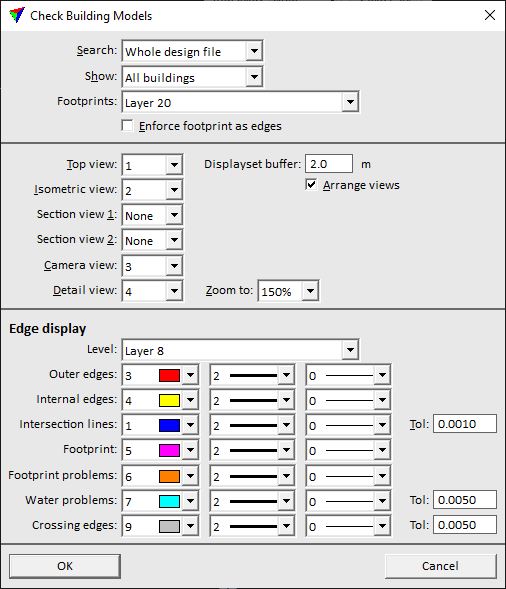
2. Define settings and click OK.
This opens the Check Building Models dialog.
SETTING |
EFFECT |
|---|---|
Search |
Area where the software searches for building models: •Whole design file - all models in the CAD file. •Active block - all models inside the active project block. This is defined by the TerraScan project block that is loaded or was last loaded into TerraScan. •Loaded point area - all models inside an area for which points are loaded in TerraScan. |
Show |
Building models shown in the list of the Check Building Models dialog: •All buildings - all building models on Model to check levels defined in Building vectorization / Levels. •Unchecked buildings - building models on Model to check levels defined in Building vectorization / Levels with the status Need to check or any "problem" status. •Problem buildings - building models on Model to check levels defined in Building vectorization / Levels with any "problem" status. See Validate models for more information. |
Footprints |
CAD file level on which the footprint polygons are drawn. This is required for detecting and highlighting Footprint problems. |
Enforce footprint as edges |
If on, the tool clips automatically all building model edges to the footprint polygons. You should switch this option on if model edges must match to footprint polygons. |
Top view |
A top view showing the active building model is displayed in the given view. |
Displayset buffer |
Elevation buffer for displaying roof points of a displayset in the Top view. This has only an effect if Points is set to Displayset only in the Display Mode dialog. |
Isometric view |
An isometric view showing the active building model. It is recommended to set the display style for this view to Smooth rendering in CAD file view controls. |
Section view 1 |
A section view showing the active building model. The section is drawn along the major direction of the building. |
Section view 2 |
A section view showing the active building model. The section is drawn across the major direction of the building. |
Camera view |
A camera view showing the active building model is displayed in the given view. This view works only if a mission, camera, and image list are loaded into TerraPhoto. |
Detail view |
A camera view showing the location of an active building model in detail is displayed in the given view. The zoom level is determined by the given Zoom to value. This view works only if a mission, camera, and image list are loaded into TerraPhoto and if you select a building edge or corner for modification. |
Arrange views |
If on, the CAD file views are arranged on the screen according to the given view settings. The software opens the views and places them within the CAD platform interface without overlap. |
Level |
CAD file level on which the colored edges of an active model are drawn. The level should be switched on in the views that display the active model. |
Outer edges |
Display color, line weight and line style of outer edges of the active model. Uses the active color table and standard line weights and styles of the CAD file. |
Internal edges |
Display color, line weight and line style of internal edges of the active model. Uses the active color table and standard line weights and styles of the CAD file. |
Intersection lines |
Display color, line weight and line style of intersection lines of the active model. Uses the active color table and standard line weights and styles of the CAD file. The Tolerance value determines up to which maximum positional difference vertices of intersecting planes are considered to be at exactly the same location. |
Footprint |
Display color, line weight and line style of lines of the footprint polygon. Uses the active color table and standard line weights and styles of the CAD file. |
Footprint problems |
Display color, line weight and line style of lines of the active model that do not match to footprint polygons. This highlights problems if a vector model edge is inside the footprint polygon drawn on the Footprints level. Uses the active color table and standard line weights and styles of the CAD file. |
Water problems |
Display color, line weight and line style of lines of the active model that is not "water tight". The Tolerance value determines the size of allowed gaps that are ignored. |
Crossing edges |
Display color, line weight and line style of edge lines that cross each other and result in roof polygons intersecting each other. The Tolerance value determines up to which maximum distance crossings of edge lines is ignored. |
The Check Building Models dialog shows a list that contains all building models drawn on the CAD file levels that are defined in Building vectorization / Levels category of TerraScan Settings. The status of each model after automatic creation is Need to check by default. In addition, the status of a model can indicate a problem. Then, the status is shown in red color. A "problem" status can be related to footprints, such as mismatch between model edges and footprint boundaries, or to non-planar roof patches.
Further, the dialog contains buttons that can be used to change the status of a model to Approved, to recompute or delete a model, to fix footprint or planarity issues, to display a certain model, and to select another image that is displayed in the background of the active model. Menu commands can be used to display the Vectorize Buildings dialog, to validate models, and to change the status of all models to Approved.
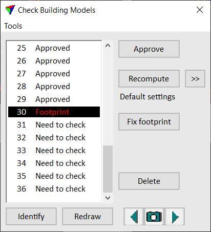
To show the location of a building model, select a line in the Check Building Models dialog. This updates the display in all views that are set up for checking building models.
Command/button |
EFFECT |
|---|---|
Approve |
After checking a building model and possibly modifying it, click on the Approve button. This changes the status of the selected model to Approved. It moves the model to the Approved models levels defined in Building vectorization / Levels category of TerraScan Settings. |
Recomputes a building model based on loaded points and tailored settings. This might be necessary, if the settings of the automatic vectorization process did not provide a reasonable model for this building. |
|
Fix footprint |
Fix small mismatch between roof edges and a footprint polygon. This is only available if models have been validated using the Footprint mismatch option. |
Fix planarity |
Fixes planarity issues of roof patches. Exactly planar roof patches are enforced. This also requires that Average elevations is set to 0.0 in Building vectorization / Models category of TerraScan Settings. Exact planarity may lead to small differences between vertices of intersection lines. This is only available if models have been validated using the Non-planar roof option. |
Delete |
Deletes a model from the CAD file and from the list. If you undo the delete action by using the Undo command of the CAD platform, the model is returned into the CAD file but not into the list of the dialog. You need to re-open the dialog in order to see the model again in the list. |
Identify |
To identify a building model, click on the Identify button and place a data click close to a model in a view. This selects the corresponding model in the Check Building Models dialog. |
|
You can use the buttons in the lower right corner in order to select images from the TerraPhoto image list. The image is displayed in the camera views used for checking building models. By default, the software selects the image for display that sees the building (detail) location best. Click on the camera button in the middle of the button group in order to identify an image for display. Move the mouse pointer into a view. The image footprint closest to the mouse pointer is dynamically displayed. Select an image for display with a data click. Click on the arrow buttons left and right in the button group in order to select the previous or next image from the currently displayed image in the images list. |
Tools / Computation settings |
Opens the Vectorize Buildings dialog with the settings used in the automatic vectorization process. This might be useful to check before recomputing a model for which the settings do not apply sufficiently. |
Tools / Validate models |
Checks building models for footprint or planarity problems. |
Tools / Sort |
Options for sorting the models in the list: •By area - by roof area. Smaller models are in the beginning of the list, larger models in the end. •By number - by model number. This is the default order of models when the Check building models tool is started. •By status - by model status. Approved models are in the end of the list. |
Tools / View fields |
Define attribute fields that are visible in the Check Building Models dialog. |
Tools / Approve all |
Changes the status of all models in the list to Approved. It moves the models to the Approved models levels defined in Building vectorization / Levels category of TerraScan Settings. |

To recompute a building model:
1. Load laser data into TerraScan for the location of the building model.
2. Click on the  button in order to open the Vectorize Buildings dialog.
The settings of the dialog are described for the Vectorize Buildings tool.
3. Change settings in the dialog and click OK.
4. Click on the Recompute button.
This recomputes the selected building model by using the tailored settings.
Validate models command checks the vector models in the list for footprint, topology and/or planarity issues. The check is useful to find models that do not match to footprint polygons or that contain non-planar building patches.
The validation process may change the status of vector models to a "problem" status:
•Footprint - the model edges do not match to the footprint boundaries.
•No footprint - no footprint is available for validation.
•Non-planar - one or more patches of the model are not planar. Exactly planar roof patches can only be created if Average elevations is set to 0.0 in Building vectorization / Models category of TerraScan Settings. Otherwise, patches are non-planar which is fine for most of the building model applications.
•Not watertight - the model is not closed, i.e. water can flow out of the model.
•Intersecting - roof polygons intersect each other.
A "problem" status is displayed in red in the list of building models.
To validate models:
1. Select Validate models command from the Tools pulldown menu.
This opens the Validate Settings dialog:
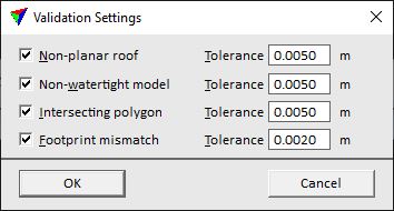
2. Select settings and click OK.
This starts the validation process. An information dialog shows the amount of detected problems. The status for models is changed in the list if a problem is detected.
SETTING |
EFFECT |
|---|---|
Non-planar roof |
If on, the process checks the planarity of roof patches. A problem is detected if the patch planarity differs more than the given Tolerance value from a perfect plane. |
Non-watertight model |
If on, the process checks for gaps in building models that allow water to flow out of the model. A problem is detected if the gap size is larger than the given Tolerance value. |
Intersecting polygon |
If on, the process checks for roof polygons intersecting each other by more than the given Tolerance value. |
Footprint mismatch |
If on, the process checks mismatch between footprint polygons and vector model edges. A problem is detected if the model vertex differs more than the given Tolerance value from the footprint vertex. |
It is virtually impossible to create roof patches with exact planarity, perfect geometry and even shapes. Therefore, enforce exact planarity for roof patches only if it is explicitly required. Otherwise, it may be more convenient to create building models with correct outer boundaries and intersection lines for roof patches and at the same time, accepting non-planar patches.
View fields command lets you select which attributes are displayed in the Check Building Models dialog.
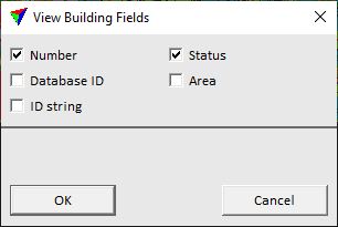
ATTRIBUTE |
DESCRIPTION |
|---|---|
Number |
Internal building number. |
Database ID |
Building ID stored in a 3D City Database. |
ID string |
Text string stored for a building in a 3D City Database. |
Status |
Modification status. |
Area |
Size of the area covered by the roof. |