

TerraScan User Guide
Vectorize Buildings
Not Lite
 Vectorize Buildings tool creates 3D building models based on loaded point cloud data. The point cloud has to be classified into:
•ground points using the Ground classification routine.
•above-ground points which may be hits on building roofs using Compute distance followed by the By distance classification routine. This classification also includes points from high vegetation and other high objects.
•points on building roofs. Buildings classification routine, and grouping-based classification routines provide suitable classification.
The tool creates models representing each building. each building has individual roof planes represented, and walls and floor extruded from roof edges to the specified offset from the ground level. The offset definition can be adjusted in Building vectorization / Model. In Bentley CAD environment the components of an individual building are bundled as Bentley cell element. In Spatix the corresponding element type is symbol.
Building vectorization can be also performed on project level by using the Vectorize buildings macro action.
To vectorize buildings based on loaded points:
1. Load point cloud data into TerraScan.
2. Select the Vectorize Buildings tool.
This opens the Vectorize Buildings dialog:
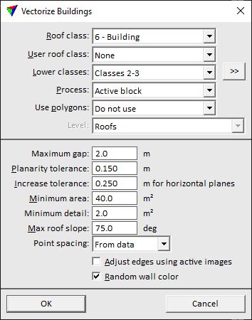
3. Define settings and click OK.
This starts the vectorization process. It may take a while until the first models are created because the routine creates models for large buildings first. The building models are drawn into the CAD file according to the settings in Building vectorization / Levels category of TerraScan Settings.
SETTING |
EFFECT |
|---|---|
Roof class |
Point class consisting points on building roofs. |
User roof class |
Point class consisting points on building roof details. The details are vectorized even if the area is smaller than the Minimum detail value. |
Lower classes |
Point class(es) consisting points next to building roof edges, for example, ground or low vegetation. The points are used to determine the base elevation of building walls and help to place outer roof edges more accurately. |
|
Opens the Select classes dialog which contains the list of active classes in TerraScan. You can select multiple source classes from the list that are then used in the Lower classes field. |
Process |
Area to be processed: •All points - all loaded points are processed. This may include points from neighbour blocks. •Active block - points of the active block are processed. •Inside fence - points inside a fence or selected polygon are processed. This is active only if a fence is drawn or a polygon is selected. |
Use polygons |
Defines how polygons are used in addition to point cloud data: •Do not use - no polygons are used. •As property boundaries - polygons define boundaries that divide large building blocks into separate models. Example: land property polygons. •As wall positions - polygons define XY shape of minimum building size. Can improve roof edge positioning when point density varies, or ground level points exist under roof classes. •As roof edges - polygons define the XY shape of outer edges of buildings. Example: footprint polygons. |
Level |
CAD file level on which the polygons are located that are used in the vectorization process. This is active only if Use polygons is set to As bounding polygons or As roof edges. |
Maximum gap |
Maximum distance between building parts belonging to the same model. If the distance is larger, separate building models are created. |
Planarity tolerance |
Defines how closely a point must match a plane equation to belong to that roof plane. |
Increase tolerance |
Additional tolerance for merging close to horizontal planes together. |
Minimum area |
Minimum size of a building footprint. |
Minimum detail |
Minimum size of a building part footprint. |
Max roof slope |
Maximum gradient of a roof plane. |
Point spacing |
Spacing between points on building roofs in the point cloud: •From data - the software derives the spacing from the data. This is the normal setting for randomly distributed point clouds. •Fixed - the spacing is given by the value in the text field. |
Adjust edges using active images |
If on, building edges are adjusted based on images. The images must be referenced by an image list loaded into TerraPhoto. |
Random wall color |
If on, wall shapes are colored randomly by using a selection of colors from the active color table of the CAD file. If off, the color defined in Building vectorization / Model category of TerraScan Settings is used for all wall shapes. |
