

TerraScan User Guide
Export raster image
Export raster image command generates a raster image where pixel values are derived from laser point attributes. The source data is points loaded in TerraScan.
The raster image can be created as Windows bitmap (.BMP), GeoTIFF (.TIF), or JPG. The color of a pixel is determined using laser points whose coordinate values fall inside the pixel. The coloring attribute can be chosen as:
•Distance - distance value based on the distance computation.
•Distance footprint - distance value based on the distance computation. Single points are sampled to multiple pixels considering the point footprint overlapping the pixels.
•Distance + intensity - distance value based on the distance computation defining the color, and intensity value the color brightness.
•Elevation - laser point elevation.
•Elevation difference - elevation difference between laser points of two different classes.
•Elevation footprint - laser point elevation. Single points are sampled to multiple pixels considering the point footprint overlapping the pixels.
•Intensity hits - laser point intensity.
•Intensity footprint - average intensity of points within a footprint area overlapping the pixel.
•Normal - direction of the normal vector relative to horizontal plane.
•Point color - color values stored for laser points.
•Point class - laser point class color specified in Define classes.
•Road intensity - intensity of laser points computed by directional sampling along road alignment vectors.
•Slope - slope gradient based on normal vector computation.
To create a colored raster image:
1. Select Export raster image command from the Output pulldown menu.
This opens the Export Raster Image dialog:
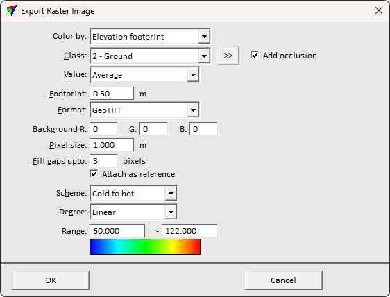
2. Define settings.
3. Click OK.
This starts the generation of the raster file and opens the Export raster image dialog, a standard dialog for saving files.
4. Define a location and name for the output file and click Save.
This creates the raster image.
SETTING |
EFFECT |
|---|---|
Color by |
Coloring attribute. See description above. |
Colors |
Opens Distance Color Scheme dialog which lets you define a distance based coloring scheme. Uses the same .DCS scheme format as Display mode. This is active only if Color by is set to Distance, Distance footprint, or Distance+intensity. |
Use |
The attribute to use as the intensity: Intensity, Amplitude, or Reflectance. This is active only if Color by is set to Intensity hits, Intensity footprint, or Road intensity. |
Class |
Point class(es) to use for creating the raster file. If Color by is set to Elevation difference, two classes must be selected. |
|
Opens the Select classes dialog which contains the list of active classes in TerraScan. You can select multiple source classes from the list that are then used in the Class field. |
Add occlusion |
If on, a shadow effect cast by foreground points is added to enhance the understanding of the scene. This is active only if Color by is set to Distance footprint, or Elevation footprint. |
Value |
Determines the value for each pixel: •Lowest - smallest value of points inside the pixel area. •Average - average value of points inside the pixel area. •Highest - highest value of points inside the pixel area. This is active only if Color by is set to Distance, Distance footprint, Distance+intensity, Elevation, Elevation difference, Elevation footprint, or Intensity hits. |
Alignments |
Level on which the road alignment vectors are located. This is active only if Color by is set to Road intensity. |
Sampling |
Value sampling method for raster creation: •Road intensity - distance along the road alignment element(s). •Normal - radius around the pixel center. •Slope - radius around pixel center. |
Footprint |
Neighborhood size the pixel affects. This is active only if Color by is set to Distance footprint, Elevation footprint, or Intensity footprint. |
Format |
Format of the output file: Windows BMP, GeoTIFF, GeoTIFF + TFW, or JPG + JGW. If using Color by: Point color, activates additional color bit depth selection for multi-band raster export. |
Background |
RGB values for pixels that do not have an attribute value. |
Pixel size |
Size of each pixel in the output file. |
Fill gaps |
If on, gaps up to the given number of pixels are filled by interpolation in places where there are no laser points inside a pixel area. |
Attach as reference |
If on, the output image is attached as a raster reference. This requires TerraPhoto to run. |
Scheme |
Type of coloring scheme for elevation or intensity coloring: •Cold to hot - varies from blue for low pixel values via cyan, green, and yellow to red for high pixel values. This is a common coloring scheme for elevation coloring. •Hot to cold - varies from red for low pixel values via cyan, green, and yellow to blue for high pixel values. •Selected colors - a user-defined coloring scheme can be created by clicking on the Define button. •Black to white - varies from black for low pixel values to white for high pixel values. This is the common coloring scheme for intensity coloring. •White to black - varies from white for low pixel values to black for high pixel values. |
Degree |
Determines how the color changes in color schemes are computed. Warm and Hot move a coloring scheme towards the red-yellow color range, Cool and Cold towards the blue-cyan color range. For gray scale images, Light moves the gray scale towards white and light gray, Dark towards black and dark gray. Linear defines even distribution of colors. |
Unit |
Defines the unit for Slope coloring: Degree or Percentage. |
Range |
Defines the value range that is covered by the color scheme for Elevation and Intensity coloring. Should be set to the general elevation or intensity range covered in the laser data to ensure that all values are represented by the complete color scheme. |

Raster images can be produced in batch mode by using the Export raster images command for project blocks.