

TerraScan User Guide
Output alignment report
Output alignment report command generates a report with information at given intervals along an alignment element. The command requires the definition of an alignment report format in Alignment reports category of TerraScan Settings.
Alignment elements can be any linear element type such as line strings, shapes, circles, etc.. The report can be seen as a table where each row corresponds to an alignment station and each column contains a specific type of information.
To create an alignment report:
1. Select an alignment element.
2. Select Output alignment report command from the Output pulldown menu.
This opens the Output Alignment Report dialog:
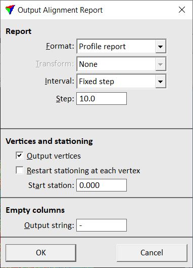
3. Define settings and click OK.
This opens the Alignment report dialog. The dialog contains the list of stations along the alignment element and the information for each station according to the alignment report definition.
You can save the report as space-delimited text file by using the Text file command, or as tabulator-delimited text file by using the Table file command from the Output pulldown menu of the dialog.
To show the location of a station, select a line in the Alignment report dialog. Click on the Show location button and move the mouse pointer into a view. This highlights the selected station with a cross.
To identify a station, click on the Identify button and place a data click close to a station in a view. This selects the corresponding line in the Alignment report dialog.
SETTING |
EFFECT |
|---|---|
Format |
Alignment report format to use. Defines the report content. |
Transform |
Transformation applied to coordinates in the report. The list contains transformations that are defined in Coordinate transformations / Transformations category of TerraScan Settings. This is active only if coordinates are included in the report. |
Interval |
Distance between two consecutive stations along the alignment element: •Fixed step - fixed distance along the whole alignment element. •Triangle edges - distance is defined by intersection points between surface triangle edges and the alignment element. This requires a surface model loaded in TerraModeler. |
Surface |
Name of the surface model. This is active only if Interval is set to Triangle edges. |
Step |
Distance between consecutive stations along the alignment element. Given in CAD file master units. This is active only if Interval is set to Fixed step. |
Min step |
Minimum distance between consecutive stations along the alignment element. Given in CAD file master units. This is active only if Interval is set to Triangle edges. |
Output vertices |
If on, the report includes the information from each location of a vertex of the alignment element in addition to the station locations. |
Restart stationing at each vertex |
If on, station values restart from Start station at each vertex location. |
Start station |
Station value at the start vertex of the alignment element. |
Output string |
Text string written into the report if a column has no valid value. |