

TerraPhoto User Guide
Airborne camera calibration
Any site with easily identifiable features on the ground is a good choice for airborne camera calibration. You would normally choose an urban area with roads and parking lots or an airfield where there are a lot of paint markings on asphalt.
If the actual project area includes such a place that fulfills the requirements of a calibration site, it is possible to use data from this place for calibration purposes. It just requires that the place is covered by the recommend Flight pattern in order to collect suitable calibration data.
TerraPhoto needs a ground model of the calibration site. Therefore, you should collect laser data during the same flight. However, you can also use a ground model from another flight.
It is beneficial but not required to have some ground control measurements from the site. They can be utilized to eliminate any systematic elevation shifts in the ground model before it is used in TerraPhoto.
For calibration, it is easiest to cover one small area with multiple crossing flight lines. This results in nearly 100% overlap between some of the images.
The same location needs to be captured from at least two different flight altitudes. This helps to differentiate some of the camera parameters from each other. The camera parameters highly correlate with each other if images from only one altitude are available.
The following figures illustrate the minimum flight pattern:
Flight pattern in a top view. |
Flight pattern in a perspective view. |
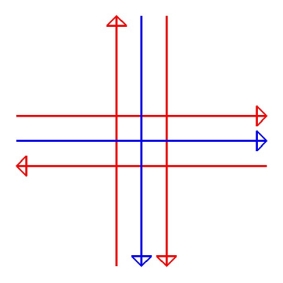
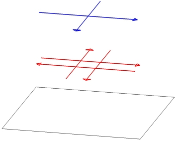
An ideal data set can be produced by flying the same site at three different altitudes, for example 500 m, 1000 m, and 2000 m.
Calibration workflow
The calibration process can be divided into three phases. The aim of the first phase is the rough positioning of the images based on reference data. In this phase, mainly the correct geographical location of the images and the overall orientation of the camera are checked. The second phase involves the manual and half-automatic placement of tie points. They are used to calibrate the misalignment angles and the principle point z value. In the third phase, the final calibration values are fixed by solving all possible camera parameters based on the tie points.
Phase 1: Camera view
A camera view makes it possible to derive reasonable values for the camera misalignment angles and the principal point z. A camera view is basically a perspective view that shows the world as seen through a camera when it was recording an image. You can compare a single raw image with laser points or 3-dimensional vector data. If the image does not match the reference data, you can change the camera parameters in order to reach a better visual match.
If the images are not even close to the reference data, you should check if the geographical position of the images in the image list is correct. Camera views are also an option for validating that all data of a project covers the same geographical location and that no errors occurred in coordinate transformations.
Camera views are described in detail in Section Create camera view. In this phase you may achieve an accuracy level of about 0.1 degree for misalignment angles.
Phase 2: Tie points for solving misalignment angles and principle point z
Tie points provide a method for calibrating most of the camera parameters. This is an iterative process. Some of the parameters can be adequately solved with a very small number of tie points while other parameters require a larger number of tie points and a data set suitable for the task. A higher number of tie points achieves a more accurate and a more reliable solution.
In the beginning, it is more laborious to enter tie points as the positioning of the images is bad. If more tie points are available, the calibration values can be gradually improved which in turn makes it faster to collect more tie points and to filter out bad tie points. The quality of the tie points is crucial to the reliability of the calibration. Therefore, it is essential to remove bad tie points during the calibration process.
As soon as you have entered a few ground tie points, it is possible to solve some of the camera parameters. You should start with the misalignment angles and then move to the principal point z. The other parameters have a much smaller effect on positional accuracy.
1. Enter tie points, enter more tie points, or filter out bad tie points.
Enter Ground tie points whenever possible. Use Air tie points only if there is no way to place Ground tie points.
Start with the manual tie point entry mode. See Tie point entry modes.
For detailed information about placing tie points see Chapter Working with Tie Points, especially commands from the Point pulldown menu and the Pixel pulldown menu.
2. Solve and apply misalignment angles using Output report command in the Tie points window.
3. Go back to step 1 and continue until the modification of misalignment angles does not improve the average mismatch of the tie points anymore.
4. Solve principal point z using Tools / Solve parameters command in the TerraPhoto camera dialog.
5. Recompute the tie points by using the Apply button in the Camera dialog.
6. Go back to step 1 until images are well-defined by tie points. See Tie point values and Tie point distribution.
If the mismatch distances for tie points become smaller (about 2-3 * pixel size of the raw images), try to switch to half-automatic tie point entry mode. See Tie point entry modes.
Continue with steps 1 to 5 until the values for the misalignment angles and principle point z do not change significantly anymore.
The second phase should result in reasonably good mismatch distances in tie points (about pixel size of the raw images).
Phase 3: Solve misalignment angles, principle point xyz, and lens distortion
The third phase of the workflow solves all camera parameters that can be calibrated with tie points.
1. Solve and apply misalignment angles using Output report command in the Tie points window.
2. Solve all other solvable parameters using Tools / Solve parameters command in the TerraPhoto camera dialog and apply the changes to the tie points.
The application adjusts roll and pitch misalignment angles if it modifies principal point x and y values. The adjustment of the misalignment angles compensates the modification of the other parameters.
You may still check for bad tie points using the Find worst command from the Tie points window.
3. Go back to step 1 and continue until there is no more improvement and the values are stable.
The third phase produces the final calibration parameters.