

TerraPhoto User Guide
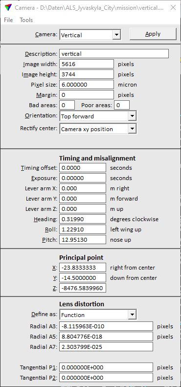
TerraPhoto camera dialog
The camera calibration values are defined in the Camera dialog of TerraPhoto that is opened by the Define Camera tool. Additionally, the dialog contains pulldown menu commands for opening and saving the camera calibration into a file, for solving camera parameters, converting from and to system-specific calibration files, and assigning bad and poor polygons to cameras.
SETTING |
EFFECT |
|
|---|---|---|
Camera |
Name of the camera for which the parameters are shown in the dialog. The camera names are available if a mission is loaded into TerraPhoto. For creating a new camera file, select Free definition. |
|
Description |
Description of the camera. |
|
Image width |
Width of an image in pixels. |
|
Image height |
Height of an image in pixels. |
|
Pixel size |
Pixel size of the camera sensor in micron. This setting is only required and takes an effect if a system-specific camera calibration is converted into a TerraPhoto calibration or vice versa. |
|
Margin |
Distance from image boundaries that are ignored for processing. Given in pixels. |
|
Panoramic |
Switch this on if panoramic images are processed. This is only active if Orientation is set to Mobile, side looking. For panoramic cameras, the Principle point X and Z, as well as the Lens distortion parameters are not available. |
|
Orientation |
General orientation of a camera relative to the movement direction: •Top forward - the top edge of images points forward. •Bottom forward - the bottom edge of images points forward. •Right forward - the right edge of images points forward. •Left forward - the left edge of images points forward. •Mobile, side looking - setting for all cameras of mobile ground-based systems. |
|
Position |
Defines the center of a rectified image for mobile system cameras. The value highly correlates with the Rectify center value. This is only active if Orientation is set to Mobile, side looking. |
|
Rectify center |
Defines the best possible position within an image for rectification: •Camera xy position - preferred setting for vertical airborne images. The option is only available if Orientation is set to any airborne camera orientation. •Image pixel - setting for oblique airborne images. The option is only available if Orientation is set to any airborne camera orientation. The Rectify center value is expressed in percent from the bottom edge of an image. For mobile system cameras, the value highly correlates with the Position value. |
|
Timing offset |
Time value in seconds that is added to the time stamps of raw images if an image is computed with the Compute list command. |
|
Exposure |
Time difference between top and bottom edge of an image. Applied by the Compute list command. |
|
Lever arm X |
Lever arm vector component. A positive value points to the right. Given in meter. |
|
Lever arm Y |
Lever arm vector component. A positive value points forward. Given in meter. |
|
Lever arm Z |
Lever arm vector component. A positive value points up. Given in meter. |
|
Heading |
Heading misalignment angle. A positive value indicates clockwise rotation. Given in degree. |
|
Roll |
Roll misalignment angle. A positive value indicates left wing up rotation. Given in degree. |
|
Pitch |
Pitch misalignment angle. A positive value indicates nose up rotation. Given in degree. |
|
X |
Principal point x position relative to the image center. |
|
Y |
Principal point y position relative to the image center. |
|
Z |
Principal point z position as a negative value. |
|
Define as |
Function type that models the lens distortion. See Lens distortion models for more information. |
|
Draw |
Draw lens distortion correction vectors of the mathematical distortion function to the CAD file. To draw the correction pattern, click Draw and place a data click pointing the desired origin position to a CAD view. |
|
Radial A3, A5 |
Constants for radial lens distortion functions. |
|
Zero radius |
Radius at which the lens distortion of a Zero radius function is 0. |
|
Radial A7 |
Constant for the radial lens distortion model of type Function. |
|
K0 ... K4 |
Constants for lens distortion models of types Balanced function, Homogenous function and Pix4d model. |
|
Tangential P1, P2 |
Constants for lens distortion functions. |
|
Columns |
Number of columns used for solving lens distortion by a Grid. |
|
Rows |
Number of rows used for solving lens distortion by a Grid. |
The measurement unit for principal point X Y Z coordinates can be pixel or millimeter or some other unit but the same must be used for all these parameters. Pixel is the recommended unit as it is easiest to understand.