

TerraPhoto User Guide
Mobile camera calibration
Any site with large buildings on two or more sides is a good choice for mobile camera calibration. The buildings should have a plane wall with easily identifiable features (such as windows, facade paintings, etc.) facing the road without obstacles in front of the wall. Long sharp edges in the images are especially useful for calibrating principle point z and lens distortion of mobile cameras.
Paint markings on asphalt add another valuable features for the calibration task. There should be enough space on the calibration site to turn around, drive back and forth, and maybe even drive crossing paths.
If the actual project area includes such a place that fulfills the requirements of a calibration site, it is possible to use data from this place for calibration purposes. It just requires that the place is covered by the recommend Drive pattern in order to collect suitable calibration data.
For calibration, it is easiest to cover one small area with multiple drive paths. This results in nearly 100% overlap between some of the images. The same building walls should be captured by each camera from at least two different distances.
The following figure illustrates an example drive pattern for a system with two side-looking cameras:
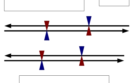
Drive pattern in a top view. Blue and red triangles indicate the views of two side-looking cameras.
The calibration process can be divided into three phases. The aim of the first phase is the rough positioning of the images based on reference data. In this phase, mainly the correct geographical location of the images and the overall orientation of the cameras are checked. The second phase involves the manual placement of tie points. They are used to calibrate the misalignment angles. In the third phase, further tie points and straight tie lines are placed in order to solve principle point z and lens distortion parameters in addition to fine tuning the misalignment angles.
Phase 1: Camera view
A camera view makes it possible to derive reasonable values for the camera misalignment angles and the principal point z. A camera view is basically a perspective view that shows the world as seen through a camera when it was recording an image. You can compare a single raw image with laser points or 3-dimensional vector data. If the image does not match the reference data, you can change the camera parameters in order to reach a better visual match.
If the images are not even close to the reference data, you should check if the geographical position of the images in the image list is correct. Camera views are also an option for validating that all data of a project covers the same geographical location and that no errors occurred in coordinate transformations.
Camera views are described in detail in Section Create camera view. In this phase you may achieve an accuracy level of about 0.1 degree for misalignment angles.
Phase 2: Tie points for solving misalignment angles
Tie points provide a method for calibrating most of the camera parameters. This is an iterative process. Some of the parameters can be adequately solved with a very small number of tie points while other parameters require a larger number of tie points and a data set suitable for the task. A higher number of tie points achieves a more accurate and a more reliable solution.
In the beginning, it is more laborious to enter tie points as the positioning of the images is poor. If more tie points are available, the calibration values can be gradually improved which in turn makes it faster to collect more tie points and to filter out bad tie points. The quality of the tie points is crucial to the reliability of the calibration. Therefore, it is essential to remove bad tie points during the calibration process.
1. Enter tie points, enter more tie points, or filter out bad tie points.
Enter Air tie points first. The calibration becomes more reliable if you also enter some Known tie points, for example, based on objects detectable in the laser point cloud.
For detailed information about placing tie points see Chapter Working with Tie Points, especially commands from the Point pulldown menu and the Pixel pulldown menu.
2. Solve and apply misalignment angles using Output report command in the Tie points window.
3. Go back to step 1 and continue until the modification of misalignment angles does not improve the average mismatch of the tie points anymore.
If the calibration is started with values of a system-specific calibration, around 20 Air tie points and 5 - 10 Known tie points should be enough to get reasonable values for the misalignment angles.
Phase 3: Solve misalignment angles, principle point z, and lens distortion
The third phase of the workflow solves lens distortion and principle point z values. It also fine tunes the misalignment angles.
1. Place a good number of Straight tie lines for each camera. See Add straight line command.
2. Check the distribution of tie points and lines by using the Draw pixel distribution command. If necessary, add more tie points/lines.
The Straight lines should be placed close to the image boundaries along edges of objects (for example building edges). The edges, which are straight in the real world, are curved in the images due to the lens distortion. Long and curved edges are best for solving the lens distortion.
3. Open the Camera dialog and set the lens distortion model to Zero radius function.
4. Set Radial A3 and A5 , and Tangetial P1 and P2 to zero. Set the Zero radius to approximately half of the image height or width, whatever is smaller.
Example: if the image size is 1624 x 1236, set Zero radius to 600.
5. Solve the lens distortion using Straight lines for all cameras of the mission with Tools / Solve parameters command in the TerraPhoto camera dialog and apply the changes to the tie points.
6. Solve principal point z for all cameras of the mission using Tools / Solve parameters command in the TerraPhoto camera dialog.
This recomputes the tie points and saves the camera files automatically.
You may still check for bad tie points using the Find worst command from the Tie points window.
7. Solve and apply misalignment angles using Output report command in the Tie points window.
8. Go back to step 6 and continue until there is no more improvement and the values are stable.
The third phase produces the final calibration parameters.