

TerraModeler User Guide
Draw Profile
 Draw Profile tool draws a profile along an alignment element. The profile shows the shape of surface models along the alignment.
The alignment element can be any linear element. Valid element types include lines, line strings, curves, arcs, ellipses, shapes, complex chains and complex shapes.
A profile is drawn as a cell element that can be freely positioned anywhere in the CAD file.
The horizontal length of the profile cell is equal to the 2D length of the alignment element. The horizontal scale represents the intended plotting scale of the profile. All text items in the profile are scaled according to the plotting scale.
The design of the elevation range grid for the profile is defined by settings in the Draw profile dialog as well as in Profiles / Elevation grid category of the TerraModeler Settings. The profile cell is drawn into the CAD file on the active level or on several levels that are defined in Profiles / Levels category of the TerraModeler Settings.
A profile can have a name written on top of the profile. The symbology settings for the name as well as for bottom row titles of specific layouts can be found in Profiles / Titles category of the TerraModeler Settings. There is also the option to add additional information at the bottom of the profile. This is defined in Profiles / Layouts category of the TerraModeler Settings.
To draw a profile:
1. (Optional) Select the alignment element.
2. Select the Draw Profile tool.
3. Identify the alignment element if it has not been selected in step 1.
The Draw profile dialog opens:
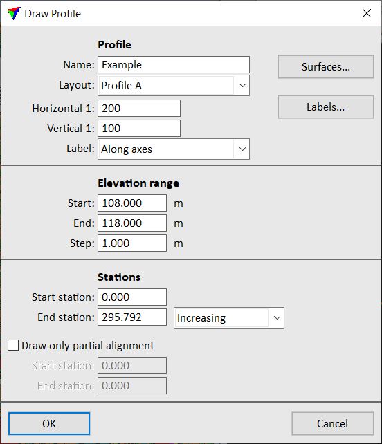
4. Define settings in the dialog.
5. (Optional) Select surfaces for being displayed in profiles using the Surfaces button. See Profile surfaces for more information.
6. (Optional) Define settings for profile labels using the Labels button. See Profile labels for more information.
7. Click OK in the Draw profile dialog.
The profile outline is displayed at the mouse pointer position.
8. Define the location of the profile cell in a CAD file top view with a data click.
This draws the profile into the CAD file.
Setting |
Effect |
|---|---|
Name |
Name drawn on top of the profile. |
Layout |
Layout scheme which defines the data rows that appear below the elevation grid of the profile: •No layout - no data row is drawn below the profile. •<layout name> - uses the selected layout scheme which has been defined in Profiles / Layouts category of TerraModeler Settings. |
Horizontal |
Horizontal scale that defines the intended plotting scale. |
Vertical |
Vertical scale that defines the elevation exaggeration as the ratio of horizontal / vertical scale. |
Label |
Position where scale labels are drawn: Along axis or Upper corner. |
Color |
Color of the elevation range grid lines and labels. |
Start |
Lowest elevation of the elevation range. |
End |
Highest elevation of the elevation range. |
Step |
Vertical step size of the elevation range. |
Start station |
Profile beginning position along the alignment element. |
End station |
Profile end position measured along the alignment element: •Increasing - station values are increasing from start to end station. •Decreasing - station values are decreasing from start to end station. |
Draw only partial alignment |
If on, the profile is only drawn for a part of the alignment defined by From station and To station. |
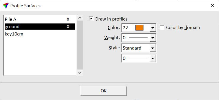
The Profile Surfaces dialog provides a list of surface models available for display in profiles. You can define which profiles are displayed and the symbology for each surface.
Setting |
Effect |
|---|---|
Draw in profiles |
If on, the selected surface in the list on the left side of the dialog is drawn in the profile. |
Color |
Line color for the selected surface. Uses the active CAD file color table. |
Color by domain |
If on, the color of domain(s) is used. See Define Domains tool for more information. |
Weight |
Line weight for the selected surface. Uses CAD file line weights. |
Style |
Line style for the selected surface: •Standard - uses CAD file standard line styles. •Custom - the user can define an own line style based on line styles and a scale. (Bentley CAD only) |
Style name (Bentley CAD only) |
Name of a custom line style. Use the Select button to select a line style definition. This is only active if Style is set to Custom. |
Style scale (Bentley CAD only) |
Scale of a custom line style. This is only active if Style is set to Custom. |
The same dialog can be opened using the Edit / Profile settings command from the Surfaces window.
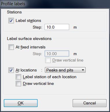
The Profile labels dialog defines settings for labeling stations and surface elevations in a profile. The symbology for bottom row labels, station labels, and elevation labels can be defined in Profiles / Labels category of TerraModeler Settings.
Setting |
Effect |
|---|---|
Label stations |
If on, the station values along the alignment are drawn below the profile. |
Step |
Horizontal step size of alignment stations that are labeled. |
At fixed intervals |
If on, surface elevation labels are drawn below the profile at fixed Steps . |
Draw vertical line |
If on, a vertical line is drawn at the location of an elevation label. This is only active if At fixed intervals is switched on. |
At locations |
If on, elevation labels are drawn at locations where there is a change in the surface model: •All triangle edges - locations where the alignment intersects a triangle edge. •Breakline edges - locations where the alignment intersects a breakline edge. •Slope changes - locations where the slope changes more than the given Change limit value. •Peaks and pits - local maximum and minimum elevations. |
Label station of each location |
If on, a station label is placed at the location of an elevation label. This is only active if At locations is switched on. |
Draw vertical line |
If on, a vertical line is drawn at the location of an elevation label. This is only active if At locations is switched on. |