

TerraModeler User Guide
Draw Section View
 Draw Section View tool creates a 3D section view that can be used for design purposes. A section view is a rotated view along a section line.
A section view is not meant to be plotted on paper. As its name implies, it is a rotated cross section view drawn at the true 3D position of the section line. This makes it ideal for design purposes. If you use a section view to place elements, they are drawn to a true 3D position.
The tool draws a line for each surface at the section’s location if the surface type is selected to be drawn in profiles. The symbology of the line is related to the surface type and determined by settings in Surface types category in TerraModeler Settings. Optionally, the elevation range can be drawn including grid lines and labels.
To draw a section view:
1. Select the Draw Section View tool.
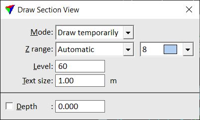
This opens the Draw Section View dialog:
2. Define settings in the dialog.
3. Enter the start point and the end point of the section line in a top view.
Continue with step 4 below.
OR
1. Select the center line element of the section view.
2. Select the Draw Section View tool.
3. Define settings in the dialog.
4. Define the section view depth by entering a data click in the top view or by defining the value in the Depth field.
5. Identify the view to be used as the section view with a data click.
6. If Z range is set to Prompt for, the Section view range dialog opens:
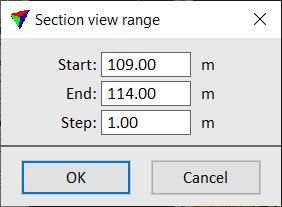
Define a Start elevation, End elevation, and vertical Step size and click OK.
The view is rotated to show the section with the section line start point on the left and the section line end point on the right. The depth of the view corresponds to the given depth value of the section.
Setting |
Effect |
|---|---|
Mode |
Drawing mode for surface section lines and elevation range in the section view: •Write to file - drawn as permanent elements. |
Z range |
Defines how the elevation range is set: •None - the elevation range is not drawn. •Automatic - TerraModeler decides the elevation range based on surface elevations. •Prompt for - the elevation range can be defined in Section view range dialog. |
Level |
CAD file level for drawing surface section lines and elevation range. |
Text size |
Text size of elevation range labels. |
Depth |
Section depth on both sides of the section line. If on, the depth is fixed to the given value. |