

TerraModeler User Guide
Draw Alignment Sections
Not Spatix
 Draw Alignment Sections tool draws cross sections along an alignment. Each cross section shows the shape of surface models at a position along the alignment. You can specify the width of the cross sections as a left and a right width perpendicular from the alignment.
The alignment element can be any linear element. Valid element types include lines, line strings, curves, arcs, ellipses, shapes, complex chains and complex shapes.
The cross sections are drawn as a group of cells that can be freely positioned anywhere in the CAD file. The arrangement of the cross sections in the group can be defined in Cross sections / Placement category of the TerraModeler Settings.
The design of the elevation range grid drawn for each cross sections is defined by settings in the Draw sections along alignment dialog as well as in Cross sections / Elevation grid category of the TerraModeler Settings. The cross section cells are drawn into the CAD file on the active level or on several levels that are defined in Profiles / Levels category of the TerraModeler Settings.
Optionally, the tool draws markers in the CAD files at places where a cross section has been generated. The section markers are placed perpendicular to the alignment element and may include a line and text elements showing the station along the alignment. The symbology of the line and text element is defined in the Alignment Section Markers dialog opened by the Markers button of the Draw Sections Along Alignment dialog.
To draw alignment sections:
1. (Optional) Select the alignment element.
2. Select the Draw Alignment Sections tool.
3. Identify the alignment element if it has not been selected in step 1.
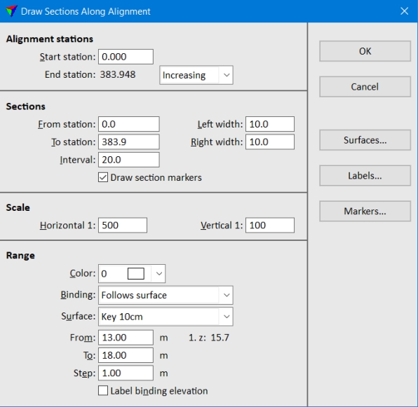
The Draw Sections Along Alignment dialog opens:
4. Define settings in the dialog.
5. (Optional) Select surfaces for being displayed in cross sections using the Surfaces button. See Profile surfaces for more information.
6. (Optional) Define settings for cross section labels using the Labels button. See Alignment section labels for more information.
7. (Optional) Define settings for cross section markers using the Markers button. See Alignment section markers for more information.
8. Click OK in the Draw Sections Along Alignment dialog.
7The cross section outlines are displayed at the mouse pointer position.
9. Define the location of the group of profile cells in a CAD file top view with a data click.
This draws the cross sections into the CAD file.
Setting |
Effect |
|---|---|
Start station |
Start station value of the alignment element. |
End station |
End station value defined by the length of the alignment element: •Increasing - stations values are increasing from start to end station. •Decreasing - station values are decreasing from start to end station |
From station |
First station on which a cross section is drawn. |
To station |
Last station from which a cross section can be drawn. |
Interval |
Station interval between two successive cross sections. Determines the number of cross sections drawn. |
Left width |
Cross section width perpendicular to the left from the alignment. |
Right width |
Cross section width perpendicular to the right from the alignment. |
Draw section markers |
If on, the location of cross sections are marked with line and text elements along the alignment element. The text elements show the station number and are placed at both end points of the marker lines. |
Horizontal |
Horizontal scale which defines the intended plotting scale. |
Vertical |
Vertical scale which defines the elevation exaggeration as the ratio of horizontal / vertical scale. |
Color |
Color of the elevation range grid lines and labels. |
Binding |
Defines how the elevation range changes along the alignment: •Stays constant - the range stays the same as for the first cross section. •Follows 3d alignment - the range is adjusted to the elevation of the alignment at the cross section location. •Follows surface - the range is adjusted to the elevation of the selected Surface at the cross section location. |
From |
Lowest elevation range value for the first cross section. The 1. z value next to the field shows the elevation value at the first cross section location. |
To |
Highest elevation range value for the first cross section. |
Step |
Vertical step size of the elevation range. |
Label binding elevation |
If on, the binding elevation is labeled by a text and a guide line in each cross section. |
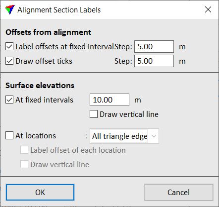
The Alignment Section Labels dialog defines settings for labeling offsets and surface elevations in cross sections. The symbology for offset labels can be defined in Cross sections / Offset labels category and for surface elevation labels in Cross sections / Elevation labels category of TerraModeler Settings.
Setting |
Effect |
|---|---|
Label offsets at fixed intervals |
If on, labels for the offset from the alignment are drawn below each cross section. The distance between offset labels is defined in the Step field. Offset values are negative to the left and positive to the right of the alignment. |
Draw offset ticks |
If on, small lines for the offset from the alignment are drawn at the bottom of each cross section. The distance between offset ticks is defined in the Step field. |
At fixed intervals |
If on, surface elevations labels at fixed Steps are drawn below the cross section. |
Draw vertical line |
If on, a vertical line is drawn at the location of an elevation label. This is only active if At fixed intervals is switched on. |
At locations |
If on, elevation labels are drawn at locations where there is a change in the surface model: •All triangle edges - locations where the alignment intersects a triangle edge. •Breakline edges - locations where the alignment intersects a breakline edge. •Slope changes - locations where the slope changes more than a given Change limit. •Peaks and pits - local maximum and minimum elevations. |
Label offset of each location |
If on, an offset label is placed at the location of an elevation label. This is only active if At locations is switched on. |
Draw vertical line |
If on, a vertical line is drawn at the location of an elevation label. This is only active if At locations is switched on. |
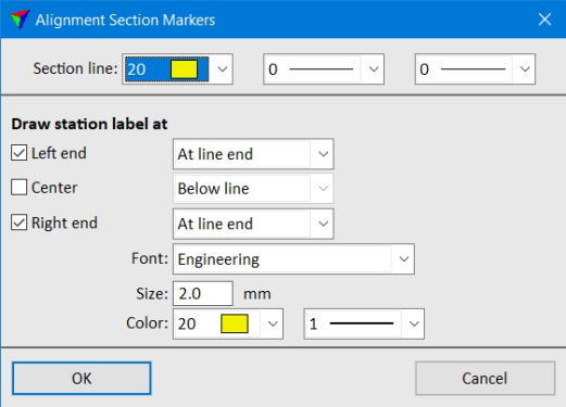
The Alignment Section Markers dialog defines settings for markers that are placed at locations where cross sections have been generated. The markers may include text elements that indicate the station along the alignment.
Setting |
Effect |
|---|---|
Section line |
Color, weight and style of the marker line. Uses the active color table and line weights/styles of the CAD file. |
Left end |
If on, a text element indicating the station along the alignment is placed at the left end of the section marker line. |
Center |
If on, a text element indicating the station along the alignment is placed in the center of the section marker line. |
Right end |
If on, a text element indicating the station along the alignment is place at the right end of the section marker line. |
Font |
Font type used for the text element. The list contains the fonts available in the CAD file. |
Size |
Size of the text element. Given in CAD file secondary units. |
Color |
Color and weight of the text element. Uses the active color table and line weights of the CAD file. |