

TerraMatch User Guide
Search cloud-to-cloud
See article Cloud to cloud matching for overview and background information of the cloud-to-cloud matching process.
Search cloud-to-cloud tie line search extracts a user defined interval of active data, and compares the interval to the selected target finding the optimal shift to improve the match. The target can be a reference point cloud, or other passes in the same, active point cloud. The tie line search contains a sanity check validating the consistency of consecutive tie line observations. The shift values of consecutive tie line observations must not differ too much, and only observations not varying too much are accepted. The tie line search uses Cloud classes specified in Define tie lines settings.
Cloud-to-cloud tie line search can use the point cloud geometry, or intensity values to solve the optimal shift for the data. The different approaches have different use cases and prerequisites:
•Xyz - point match - method optimizes the shift minimizing the distance between the points in the data slice and target. This method does not require initial classification, but excluding objects appearing only in either data, like moving objects, can improve the result. This method is suitable for point clouds with plenty of fully 3D objects such as city environment with walls, fences, poles, trash cans etc.
•Xyz - elevation grid - method computes elevation rasters from the active data and the target data, and optimizes shift minimizing the difference between the two rasters. This suits well for high point density data that contains elevated features. Suitable features could be, for example, curbstones, or rails. This does not require significant preclassification of data, but excluding changes, like moving object, from Cloud classes may improve the result.
•Xy - intensity - method computes intensity rasters from the active data and the target data, and optimizes the horizontal shift by matching the patterns visible in point cloud intensity. For example, road paint markings could be used for matching with this option. The Cloud classes should contain all points on the surfaces representing the useful features.
•Xy - point match - method aims to pair classified landmark points in the active data and matching target, and optimizes horizontal shift to make the landmark points match. The Cloud classes should contain the landmark points classified for matching. The landmark points could, for example, represent tree highest points in ALS data.
If computing the observations against reference point cloud, the reference information must be loaded or defined. See Reference project exists option in the Project information dialog of TerraScan. If loaded points are used, the reference points can be loaded into TerraScan with the Read reference points command. If a project block is loaded, the Load reference points option must be switched on.
The resulting tie lines are useful for computing a fluctuating XY(Z) correction curve for the data using Find tie line fluctuations.
To search cloud-to-cloud tie lines:
1. Select Search cloud-to-cloud command from the File pulldown menu of the Tie line window.
This opens the Search Cloud-to-cloud Tie Lines dialog:
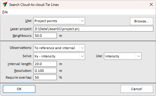
2. Define settings and click OK.
The software starts the search for tie lines. As a result, tie lines are added to the list of active tie lines. The number of tie lines found is displayed in an information dialog after the search is completed.
The tie lines are displayed on top of the point cloud. Use Display mode options to change the appearance, for example, to color the tie lines based on the mismatch magnitude for result consistency validation.
Although the tie lines can be displayed on top of the point cloud, there is not much use in checking the tie lines. Each tie line drawing just represents the given time interval for which the software tries to compute the XYZ shift. The tie line drawing does not represent any specific XYZ location in the point clouds.
3. Use the Find tie line fluctuations tool in order to compute, check, and save the XYZ correction curve for matching.
Setting |
Effect |
|---|---|
Use |
Laser points used for placing the tie lines: Project points (not UAV) or Loaded points. |
Laser project |
Path to a TerraScan project. This is only active if Use is set to Project points. |
Neighbours |
Buffer for loading points from neighbouring blocks. Aim to buffer size covering full flightline width, and the Interval length of data capture. This is only active if Use is set to Project points. |
Observations |
Whether to compare active data to reference only, or search internal observations evaluating the match to other moment in time inside active data, too. Reference observations help improve the positioning accuracy and match to reference, while internal observations help reducing mismatches caused by positioning drift. •To reference - search finds observations comparing to reference data only. •To reference and internal - search finds observations comparing active data to the reference, and active data to other moment in time inside active data. •Internal - search finds observations comparing an interval of active data to another moment in time inside active data |
Solve |
Shift optimization method for comparing the match. •Xyz - point match - minimize mismatch between points in active data and reference. Suitable for environments containing above ground features, like poles or traffic signs. •Xyz - elevation grid - minimize mismatch using surface elevation pattern. Suitable for environments with surface features, like curbstones, rails or other objects. •Xy - intensity - minimize horizontal mismatch using intensity values. Suitable for environments with intensity variations, like paint markings on road surface. •Xy - point match - minimize horizontal mismatch between landmark points. Suitable for using tree top points for matching ALS data, for example. |
Use |
The attribute to use as intensity, Amplitude, Intensity, or Reflectance. This is available only if Solve is set to XY - intensity. |
Interval length |
Difference between consecutive tie lines. Adjusts the size of the slice used in tie line search. |
Resolution |
The resolution specifies the shift increment size. Adjust to correspond the point cloud density. In general, 10 centimeter for ALS data, and 2 cm for MLS data are reasonable values. |
Search radius |
Tolerance for pairing active and target data. Points varying more than the tolerance are not considered in optimization. Adjust corresponding the data quality. Use bigger values for less precise data. Use more strict tolerance if Cloud classes contain more outliers that should not be paired between the active data and matching target data. |
Require overlap |
The percentage the target data must cover a single time slice of the active data to extract a tie line. If active position is not covered enough, the extraction will skip the position and continue to the next data slice. Use higher value for more robust observations. |
Use File / Load settings or Save settings as commands to import or store the search options in a file. Use the setting file with Search tie lines macro action to search tie lines in project scale.
The saved settings include some options, like class selection, specified in separate tie lines settings dialog.