

TerraMatch User Guide
Display mode
Display mode command lets you define how tie lines are drawn in different CAD file views. For each view, you can select the coloring method, line weight, and limit the display of tie lines to certain criteria. The different modes are useful for identifying observation coverage, and anomalies in mismatches, for example.
To set the display of tie lines:
1. Select Display mode command from the View pulldown menu.
This opens the Tie line display mode dialog:
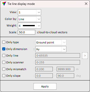
2. Define settings and click Apply.
This applies the settings to the selected view. You can continue with the definition of settings for another view.
Setting |
Effect |
|---|---|
View |
Number of the CAD file view for which the settings are applied. The list contains view numbers 1-8. |
Color by |
Determines the coloring method: •Do not draw - no tie lines are draw. •Line - tie lines are colored by line number. •Scanner - tie lines are colored by scanner number. This makes only sence if tie lines are collected separately for different scanners. •Slope - tie lines are colored by the angle between the observation and the horizontal plane. •XYZ mismatch - tie lines are colored by the mismatch magnitude. •XY mismatch - tie lines are colored by the magnitude of horizontal mismatch. •Z mismatch - tie lines are colored by the magnitude of vertical mismatch. |
Define |
Define color scheme for tie line coloring. Available only if Color by is set to Slope or mismatch. |
Weight |
Line weight for drawing tie lines. The list contains the line weights of the CAD platform. |
Scale cloud-to-cloud vectors |
Multiplier for scaling the cloud-to-cloud tie line pull vectors visually. Adjust the value to visualize the vectors in interpretable size. |
Only type |
If on, only tie lines of the given type are drawn: •Any known - tie lines of any “known” tie line type, such as Known xyz, Known xy, Known z, Known line. •Any common - tie lines of any tie line type that is not “known”. •<type> - tie lines of the selected type. |
Only dimension |
If on, only tie lines of the given dimension are drawn: •Xyz - tie lines that provide full 3D (XYZ) control. •Xy - tie lines that provide horizontal (XY) control. •Z - tie lines that provide vertical (Z) control. |
Only line |
If on, only tie lines of the given line number(s) are drawn. You can define several line numbers by using minus and comma, for example, 1-5,7,10. |
|
Use the Pick visible line button to identify a trajectory line by a data click. The number of the line closest to the data click is used in the Only line field. |
Only scanner |
If on, only tie lines of the given scanner number(s) are drawn. You can define several scanner numbers by using minus and comma, for example, 1-3,5. |
Only mismatch |
If on, only tie lines within the given mismatch value range are drawn. Define the minimum and maximum mismatch value for drawing tie lines in the text fields. |
Only slope |
If on, only tie lines with the given slope value range are drawn. Define the minimum and maximum slope value for drawing tie lines in the text fields. 0.0 refers to horizontal, 90.0 to vertical direction. Tie points are not drawn if this option is on. |
