

TerraMatch User Guide
Working with tie lines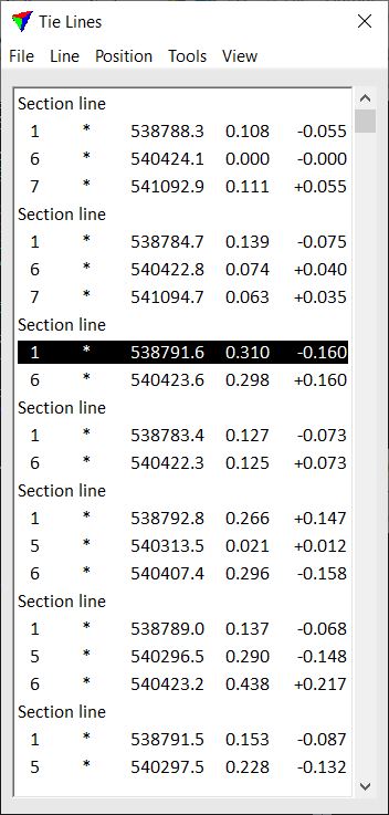
Tie lines are correspondence observations representing known points or surfaces on different lines or moments in time. Tie lines are useful for solving corrections, reporting mismatches, and visualizing mismatches.
The tie line mode is started with the Define Tie Lines tool. The tool opens the Tie lines window.
The window provides pulldown menus with commands for working with tie lines. These commands are described on the following pages. If a tie line file is loaded, it shows for each tie line the tie line type and the following information in columns 1-5:
1 strip number
2 scanner number
3 time stamp
4 XY mismatch at tie line location
5 Z mismatch at tie line location
The Define Tie Lines tool can also arrange the views in the CAD file in a way that is suitable for working with tie lines. The view setup includes:
•Full view - all tie lines are displayed in a top view.
•Entry view - one selected tie line position is displayed in a horizontal section or top view. This view is used for viewing or placing close-to-horizontal tie lines manually.
•Detail view - one selected tie line with all its positions is displayed in a horizontal section or top view.
•Wall entry view - one selected tie line position is displayed in a vertical section view. This view is used for viewing or placing close-to-vertical tie lines manually.
•Wall detail view - one selected tie line with all its positions is displayed in a vertical section view.
The views are updated automatically depending on the selected tie line type.
Asterisk symbol in the scanner column indicates points from multiple scanners were used to fit the observation