

TerraScan User Guide
By centerline
Not Lite
By centerline routine classifies points based on their distance to a linear element.
The linear elements that are used by this routine can be lines, polylines (Spatix) or line strings (Bentley CAD), arcs, polygons (Spatix) or shapes (Bentley CAD), big elements (Spatix) or complex elements (Bentley CAD) consisting valid simple element types. The classification is performed by using either selected elements or elements on a specified CAD file level.
If multiple elements are used, each laser point is classified according to the offset distance to either the closest linear element or to any of the linear elements. In addition to the 2D distance, the elevation distance can be included in the classification process. Further, the classification can be limited to a certain longitudinal distance from vertices, which is useful, for example, to classify points along a line string but only in a certain area around vertices.
SETTING |
EFFECT |
|---|---|
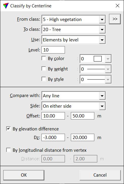
From class |
Source class(es). |
|
Opens the Select classes dialog which contains the list of active classes in TerraScan. You can select multiple source classes from the list that are then used in the From class field. |
To class |
Target class. |
Use |
Defines what elements are used: •Selected linear elements - any selected elements in the CAD file. This requires the selection of elements before starting the routine. •Elements by level - any elements that are located on a given CAD file level. |
Level |
Number of the CAD file level where elements are located that are used for the classification. This is active only if Use is set to Elements by level. |
By color |
If on, elements on the given Level are further filtered by the selected color. Click on the color field in order to select the color. Uses the active color table of the CAD platform. This is active only if Use is set to Elements by level. |
By weight |
If on, elements on the given Level are further filtered by the selected weight. Click on the list of line weights in order to select the weight. Uses the line weights of the CAD platform. This is active only if Use is set to Elements by level. |
By style |
If on, elements on the given Level are further filtered by the selected style. Click on the list of line styles in order to select the style. Uses the line styles of the CAD platform. This is active only if Use is set to Elements by level. |
Compare with |
Method of comparing points to linear elements: •Any line - points are classified if they are within the distance of any linear element. •Closest line - points are classified if they are within the distance of the closest linear element. |
Side |
Side on which to classify points: On left side, On either side, or On right side. The side is relative to the digitization direction of the linear element. |
Offset |
Minimum and maximum 2D distance. Points within the offset range are classified. |
By elevation difference |
If on, only points within the given elevation distance range from the linear element are classified. Define the elevation offset in the Dz fields. |
By longitudinal distance from vertex |
If on, only points within the given longitudinal distance range from the closest element vertex are classified. The longitudinal distance is measured in both directions from a vertex along the linear element. Define the distance in the Distance fields. |
