

TerraScan User Guide
Draw Sign Visibility
 Draw Sign Visibility tool determines from what points a target object, such as a traffic sign, traffic light, advertisement plate, etc., are visible. With other words, the tool also finds points on objects that may obstruct the sight to a target object.
The process requires a shape, ellipse, or complex shape element that represents the target object. The element must be drawn in a way that its front side faces towards the viewer. This means, for example, that the element must be drawn in counterclockwise direction in Bentley CAD. You can digitize the shape element in a section view created with the Draw Vertical Section tool. The centerline of the section has to be at the target object’s location.
Further, the process requires a linear element drawn in driving direction that defines the path of the viewer. For instance, a trajectory line draped on the ground elevation by the Drape Linear Element tool can be used for this purpose. The viewer height is defined with a constant value in the tool’s settings.
Potential obstacles for the visibility of a target object are represented in the point cloud. The points should be classified into a ground class by using preferably the Hard surface and/or Ground classification routines and above-ground classes. To get a reliable result from the visibility analysis, any points below the ground, from moving objects, and noise in the air should be classified into separate classes. These classes can be excluded from the process.
Draw Sign Visibility tool can run on loaded points as well as on TerraScan project points. The process checks if there is any point in the point cloud close to a straight line from a viewer position to the target object. It creates point elements as markers for each analyzed location. The color of the marker indicates whether the target object is visible or not from the analyzed location. In addition, the process can draw line elements for locations from which the visibility is obstructed into the CAD file. These line element can then be used to classify points close to them using the By centerline classification routine. The classification helps to identify obstacles in the point cloud.
To analyze sign visibility:
1. Create a line element along the lane centerline as viewer traveling path.
2. Drape the line element(s) to the ground on the road surface.
3. Digitize a shape element that represents the target object.
4. (Optional) Load points into TerraScan if you want to run the tool on loaded points.
5. Select the line element that defines the viewer traveling path.
6. Select Draw Sign Visibility tool.
This opens the Draw Sign Visibility dialog:
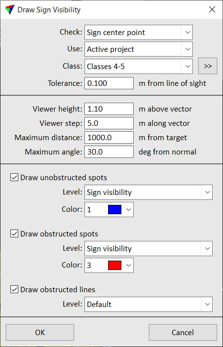
7. Define settings an click OK.
8. Identify the target object by placing a data click close to the shape element in the section view.
9. Accept the selection with another data click.
This starts the visibility analysis process and draws the visibility markers into the CAD file. An information dialog shows the success of the process.
SETTING |
EFFECT |
|---|---|
Check |
Determines the area on the target object that is checked for visibility: •Sign center point - the center point of the target object shape. •All sign vertices - the vertices of the target object shape and thus, the complete target object area. |
Use |
Laser points used for the visibility analysis process: •Loaded points - points loaded into TerraScan. •Active project - points referenced by the active TerraScan project. Not UAV |
Class |
Point classes that are included in the visibility analysis. This should include all points on potential obstacles. The list contains the active classes in TerraScan. |
|
Opens the Select classes dialog which contains the list of active classes in TerraScan. You can select multiple source classes from the list that are then used in the Class field. |
Tolerance |
Radius around a straight line between viewer and target position within which a laser point may be considered an obstacle. |
Viewer height |
Height of the viewer above the viewer path element. |
Viewer step |
Distance between locations along the viewer path element where the software analyzes the visibility of the target object and places a visibility marker. |
Maximum distance |
Maximum distances from the target object considered in the visibility analysis. |
Maximum angle |
Angle off from the normal direction of the target object shape. Defines the area that is analyzed regarding visibility obstacles. |
Short distance |
Defines the maximum value of a critical sight distance. Sight distances smaller or equal to the given value can be labeled with a different color in order to highlight the locations. |
Draw unobstructed spots |
If on, point elements are drawn into the CAD file that mark locations of unobstructed visibility. The markers are drawn on the given Level and with the given Color. |
Draw obstructed spots |
If on, point elements are drawn into the CAD file that mark locations of obstructed visibility. The markers are drawn on the given Level and with the given Color. |
Draw obstructed lines |
If on, lines are drawn from viewer position to target object if the visibility is obstructed. The lines are drawn on the given Level and using the active symbology settings of the CAD platform. |

You can undo the creation of sign visibility markers and lines by using the Undo command of the CAD platform.