

TerraScan User Guide
Write to design file
Write to design file command draws points loaded in TerraScan permanently into the CAD file. The command uses drawing rules assigned to point classes. See Define Classes tool for information about class definitions.
The points drawn into the CAD file can be colored by the following methods:
•Active symbology - the active color of the CAD file is used for all points.
•Class - colors are defined in the active class file of TerraScan. See also Color by Class display mode for points.
•Elevation - colors are determined by the elevation values of points. The coloring scheme can be changed by clicking on the Colors button. See also Color by Elevation display mode for points.
•Line - colors are determined by the line numbers of points. The colors can be changed by clicking on the Colors button. See also Color by Line display mode for points.
•Intensity - colors are determined by the intensity values of points. The coloring scheme can be changed by clicking on the Colors button. See also Color by Intensity display mode for points.
•Point color - colors are determined by color values assigned to points.
To write points to the CAD file:
1. Select Write to design file command from the Output pulldown menu.
This opens the Write to Design dialog:
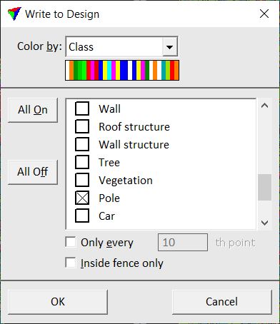
2. Define settings and click OK.
This draws the points into the CAD file.
SETTING |
EFFECT |
|---|---|
Color by |
Coloring method. |
Color |
Opens the dialog for selecting colors or a coloring scheme. This is active only if Color by is set to Elevation, Line or Intensity. |
Classes |
Point class(es) to draw into the CAD file. The list includes the active classes in TerraScan. You can switch all classes on or off by using the All On and All Off buttons. |
Only every |
If on, only every n th point is drawn into the CAD file where n is the given number of points. |
Inside fence only |
If on, only points inside a fence or selected polygon are drawn into the CAD file. |
You can undo the drawing of points by using the Undo command of the CAD platform.