

TerraPhoto User Guide
Rectify mosaic
Not Lite
Rectify mosaic command starts the production of an orthophoto mosaic.
Various rectification settings control the quality and the speed of the rectification process. TerraPhoto can produce lower quality ortho photos very fast. In contrast, if you select the highest quality options, the application uses a more complex process which takes a longer time. The different settings are illustrated in Chapter Orthophoto Production.
The process requires the selection of rectangular shape elements prior to starting the command. The rectangular shapes specify the tiles of the resulting orthophoto mosaic. They are preferably created with Place tile array command or Place Tile Array tool in TerraPhoto, but any CAD platform tool the produces rectangular shapes can be used as well.
To create an ortho photo mosaic:
1. Use any Selection tool of the CAD platform in order to select tile shapes and (optional) text elements for naming the tiles.
2. Select Rectify mosaic command from the Rectify pulldown menu.
This opens the Rectify Selected Tiles dialog:
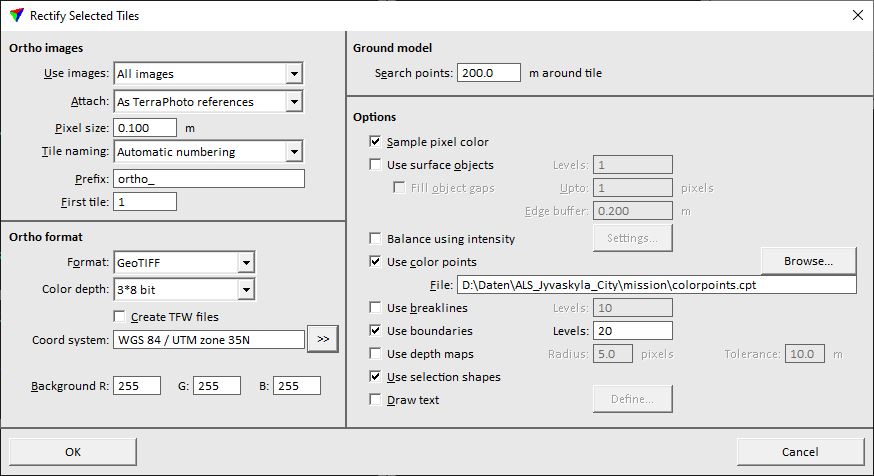
3. Define settings and click OK.
This starts the rectification process. The software produces one orthophoto for each selected tile.
SETTING |
EFFECT |
|---|---|
Use images |
Raw images to use: All images or Selected. |
Attach |
Defines how to display the produced ortho images: •Do not attach - no display. •As TerraPhoto references - attach and display as reference files in TerraPhoto. |
Pixel size |
Pixel size of the orthophotos. This should be the same or a multiple of the pixel size used when creating the tiles. |
Tile naming |
Tile naming method. In addition to user-defined tile naming schemes, you can select from: •Automatic numbering - application assigns increasing numbers to tiles in selection order. •Selected names - a selected text element inside each tile is used. •Selected numbers - a selected numerical text element inside each tile is used. User-defined tile naming schemes are defined in Tile naming schemes of TerraPhoto Settings. |
Prefix |
Text that is included in the tile names before the numbering or the selected text elements. |
First tile |
Number of the first selected tile. This is only active if Tile naming is set to Automatic numbering. |
Format |
Raster file format to produce: ECW compressed, GeoTIFF, or JPEG2000. If a GeoTIFF file exceeds the size of 4 GB, a BigTIFF file is written. |
Alpha channel |
If on, pixels with no data are stored transparent. Available only if Format is set to ECW compressed, or JPEG2000. |
Ratio |
Compression ratio for ECW compressed or JPEG2000 files. |
Datum |
Datum information that is written in the header of ECW compressed and JPEG2000 files. Commonly used datum names can be selected by using the Select button. |
Projection |
Projection information that is written in the header of ECW compressed and JPEG2000 files. Commonly used projection names can be selected by using the Select button. |
Color depth |
Defines how color values are stored in GeoTIFF files: 8 bit, 3*8 bit, 3*16 bit, 4*8 bit, 4*16 bit. |
Create EWW/TFW files |
If on, external georeference files, world files, are created with the mosaic tiles. The files have the extension .EWW or .TFW depending on the Format. |
Coord system |
Coordinate system information that is written in the header of GeoTIFF files. Commonly used coordinate system names and EPSG numbers can be selected by using the >> button. |
|
Opens the Select coordinate system dialog which contains a list of common coordinate system names and their EPSG numbers. The dialog lets you also specify the Unit for writing GeoTIFF files. |
Background R G B |
RGB color values for locations outside the image area. Values can range from 0-255 for 8-bit color depth images and from 0-65535 for 16-bit color depth images. |
Search points |
Margin around each tile for searching ground model points. |
Sample pixel color |
If on, the pixel color for the orthophoto is computed by sampling a circular area of the raw image. |
Use surface objects |
If on, true orthophotos are produced using shapes from given Levels in addition to the rectification surface. |
Fill object gaps |
If on, small gaps Up to the given amount of pixels next to surface objects in true orthophotos are filled. This is only active if Use surface objects is switched on. |
Edge buffer |
Distance from the edge of a 3D object within which object pixels are not rectified on the ground. The prevents, for example, roof pixels to be rectified on the ground next to buildings. This is only active if Use surface objects is switched on. |
If on, the intensity value of laser points is used to correct the image pixel brightness. This is useful, for example, to create orthophotos from mobile images seeing the road surface. If the intensity is of good quality, this may result in seamless orthophotos without additional color point work. Use the Settings button in order to define the settings for the brightness correction. |
|
Use color points |
If on, color points from the selected File are used to balance brightness and color differences between images. |
Use breaklines |
If on, breaklines from the given Levels are add to the ground model and thus, included in the rectification process. |
Use boundaries |
If on, polygons from the given Levels are used to limit the area that is filled with raw image information. Pixels outside the polygons are filled with the given Background RGB color. |
Use depth maps |
If on, depth maps are used for rectifying pixels at their true location. The option enables the production of true orthophotos without vector data. The depth maps should be computed only from point classes representing high objects, such as building roofs and bridges. |
Radius |
Radius checked in image depth map to find out if the rectification surface is visible or occluded. This is only active if Use depth maps is switched on. |
Tolerance |
Allowed depth difference between a rectification pixel and depth map before the point is considered occluded. If the depth of a rectification pixel is bigger than depth map value and tolerance together, pixel in the image is considered occluded and some other image is used in rectification. This is only active if Use depth maps is switched on. |
Use selection shapes |
If on, selection shapes stored in the active CAD file are used in the rectification process. |
Draw text |
If on, a text is burned into each ortho photo. This can be used, for example, to at a watermark to all orthophotos. The text as well as size, color, transparency, and position of the text can be set by using the Define button. |

The option uses the intensity value of laser points in order to correct the image pixel brightness. In fact, the result is a combination of orthophoto and intensity image. If there are gaps between camera images, they are closed by intensity information. This requires the availability of laser data with intensity values (optionally classified) and an intensity color scheme file stored from the Display mode dialog of TerraScan. The option is useful for creating orthophotos from mobile images seeing mostly the road surface. Intensity of laser data does not suffer from shadows or sun illumination, as mobile images are doing. If the intensity is of good quality, this may result in seamless orthophotos without additional color point work.
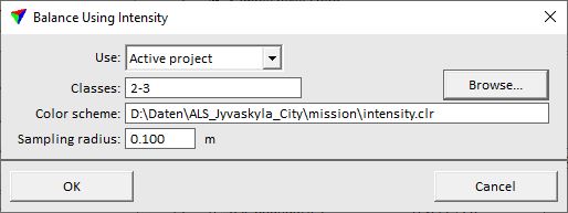
To define settings for the balancing, click on the Settings button. This opens the Balance Using Intensity dialog:
SETTING |
EFFECT |
|---|---|
Use |
Defines how laser points are used: •Loaded points - intensity values are derived from points loaded in TerraScan. •Active project - intensity values are derived from a point cloud organized in a TerraScan project. Not UAV |
Classes |
Laser point classes that are used for the correction value computation. Especially for mobile images seeing the road surface it is recommended to use only the class(es) representing points on the road surface (e.g. ground or hard surface). |
Color scheme |
Intensity color scheme file used for mapping gray values to intensity values. Such a file can be created in the Display mode dialog of TerraScan. |
Sample radius |
Circular area from which the brightness value of a pixel is derived by averaging the intensity values of all points. The recommended value is a bit bigger than the scan line spacing of the point cloud. The sample area should be big enough to cover points from several scan lines. The bigger the value, the longer the process to produce orthophotos. |