

TerraModeler User Guide
Triangulate Breaklines and Mass Points
 Triangulate breaklines and mass points tool selects model keypoints from TerraScan active points representing ground, identifies model breaklines, and triangulates a TerraModeler surface. In addition to point cloud input, the triangulation can consider existing model breaklines in triangulation. This tool is useful for streamlining the surface model creation process, and surface model optimization when working with dense, high precision point cloud data.
To extract breaklines and mass points, and triangulate a surface:
1. Prepare data for triangulation. Classify ground level points to use. If using existing breakline elements in triangulation, prepare and save an element triangulation rule file using the Triangulate Elements -tool.
2. Select the Triangulate breaklines and mass points tool.
This opens the Triangulate Breaklines and Mass Points dialog:
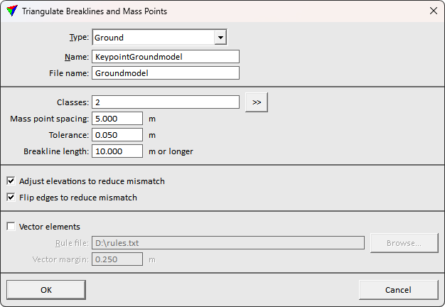
3. Define settings and click OK.
The Triangulate surface dialog opens. Follow the common steps for Creating a surface model.
The ready surface appears in Surface dialog list and written on disk after the process finishes.
Setting |
Effect |
|---|---|
Type |
The surface type to use in surface metadata. |
Name |
The surface display name. |
File name |
The surface file name to store on disk. |
Classes |
The TerraScan point class(es) to use in surface creation. >> button opens a dialog for selecting multiple classes. |
Mass point spacing |
The minimum point density. Keypoint selection begins with this spacing, and adds more points to surface if needed. |
Tolerance |
Maximum vertical tolerance allowed between the original ground point class, and the resulting surface. |
Breakline length |
Minimum breakline length to consider useful. Shorter breakline findings are neglected. |
Adjust elevations to reduce mismatch |
If on, the triangulation tries shifting surface points vertically to find optimal surface representing the point cloud. |
Flip edges to reduce mismatch |
If on, the triangulation tries alternative triangle edge directions in addition to solution with shortest triangle edges. The triangulation better optimizes the fit to point cloud. |
Vector elements |
If on, breakline elements drawn in CAD are used in surface triangulation. |
Rule file |
The breakline rule file specifying how elements are used in model triangulation. Use the Triangulate Elements tool to prepare a rule file. |
Vector margin |
The buffer around vector breakline elements. The point cloud is not used in surface creation within this buffer from the vector breaklines. |