

TerraModeler User Guide
Regions
Not Lite, Not UAV
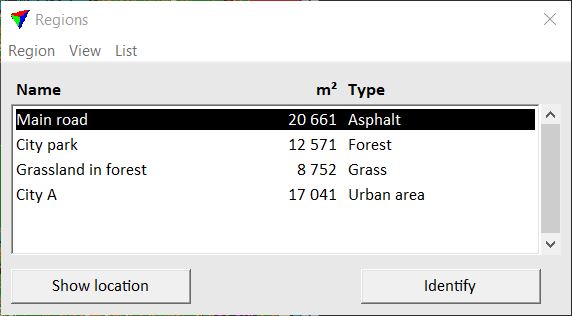
 Regions tool opens the Regions window. The window contains a list of regions that are currently defined in the CAD file. The window’s menu includes commands for creating, modifying, and deleting regions, and for creating output files of the region list.
To |
Choose menu command |
|---|---|
Create a new region |
|
Modify the information for a region |
|
Move the center point of a region |
|
Assign a new boundary to a region |
|
Delete a region |
|
Modify the size of the window |
View/Small dialog View/Medium dialog View/Large dialog |
Define fields that are displayed in the list |
|
Sort the list of regions |
|
Create output files for the list of regions |
Create command performs the same action as the Create Region tool.
Edit information command performs the same action as the Edit Region Info tool.
Move center point command performs the same action as the Move Region Center tool.
Assign new boundary command defines a new boundary to a region. The new boundary must be a closed shape element.
To assign a new boundary to a region:
1. Place the new boundary as shape element.
2. Select the region in the Regions window.
3. Select Assign new boundary command from the Region pulldown menu.
4. Identify the new boundary shape with a data click.
5. Accept the selected boundary.
This assigns the new boundary to the selected region. The boundary type changes to Shape for this region. Use Update Regions tool in order to see the changes in the CAD file.
Delete command deletes a region definition. The region definition must be selected in the list of regions.
To delete a region:
1. Select the region in the Regions window.
2. Select the Delete command from the Region pulldown menu.
The software asks you to confirm the deletion process.
3. Click Yes in the alert dialog.
This deletes the region definition and all related elements.
The Delete command can perform the same action for all regions as the Delete Region tool.
Fields command lets you choose the fields that are displayed in the Regions window. The fields show the information stored for each region, such as number, name, information, size, type, if a region forms a hole within another region, title format and boundary status.
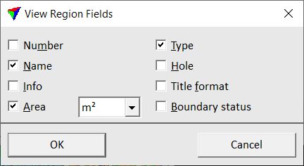
If the information for a field is not displayed completely in the list, you may enlarge the Regions window by using the commands from the View pulldown menu.
Sort by command sorts the list of regions according to the selected attribute:
•Name - ascending alphabetical order of region names.
•Number - ascending by region number, the smallest number is displayed first in the list.
•Type - ascending alphabetical order of region types.
•Area - descending by region size, the largest region is displayed first in the list.
Regions command provides several options for the output of the list. The output options include:
•Picture - the list is drawn as cell element into the CAD file. The list can include a color field and/or an area pattern field which illustrate the symbology of the different regions. (Bentley CAD only)
•Text file - a simple text file is created where fields are delimited by spaces.
•Table file - a text file is created where fields are delimited by a tab.
The output can either contain each region of the list or summarize regions of the same type. Depending on the output settings, the list can include information such as type, name, area, count of regions per type, total area per type, color field, area pattern field.
To create output of the region list:
1. Select the Regions command from the List pulldown menu.
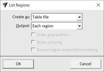
The List regions dialog opens:
2. Define settings and click OK.
3. If Create as is set to Picture, move the mouse pointer inside a top view. Define the location of the region list by a data click.
OR
4. If Create as is set to Text file or Table file, a standard Windows dialog opens for saving a file. Define a location on a hard disk in order to store the text file.
Setting |
Effect |
|---|---|
Create as |
Type of the output: •Picture - draws the list of regions as a cell element into the CAD file. •Text file - saves a space-delimited text file. •Table file - saves a tab-delimited text file. |
Output |
Defines how regions of the same type are included in the output: •Each region - the output includes a line for each region. •Region type totals - the output includes a line for each region type, the areas of regions of the same type are summarized. |
Draw area pattern |
If on, the list output includes an area pattern field for each region (type). This is only active if Create as is set to Picture. |
Draw coloring |
If on, the list output includes a color field for each region (type). This is only active if Create as is set to Picture. |
Round regions areas before adding |
If on, the region sizes are rounded before they are summed up for the total size. This is only active if Output is set to Region type totals. |