

TerraModeler User Guide
Compute Section Quantity
Not Lite
 Compute Section Quantity tool lets you attach section templates to station ranges along an alignment element. This template list can be used for computing quantities and for generating an excavation based on the cross section templates. The section templates must be defined with the Define Section Templates tool before they can be used for section quantity computation.
The alignment can be defined by a linear element, such as a 3D line string or complex chain. The area of calculation is limited by the extensions of the alignment element and the section template(s).
The excavation is computed related to one or two surfaces. The surfaces can be defined by surface models loaded in TerraModeler.
The results of the computation are shown in the tool’s dialog. They can be presented graphically in the CAD file and a text report can be stored as well.
To attach templates to an alignment:
1. Select an alignment element.
2. Select the Compute Section Quantity tool.
The Define Alignment Section Templates dialog opens:
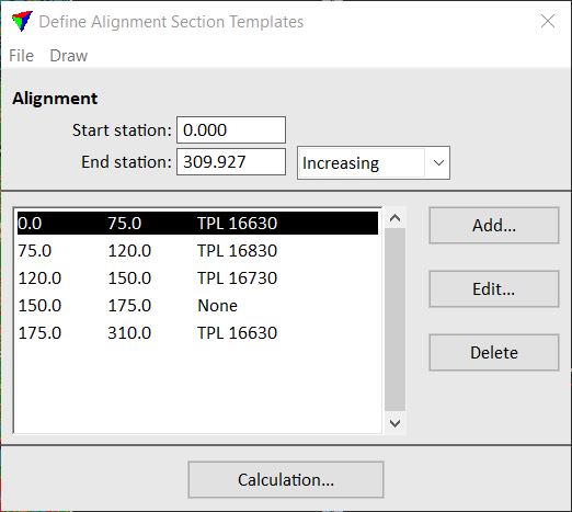
The template list contains rows with a station value range and the name of an assigned section template. A gap between station ranges of successive rows is interpreted as a linear transformation between two template types. You can skip a station range by selecting template type None. Such a station range is not included in the calculation.
Setting |
Effect |
|---|---|
Start station |
Station value at the start point of the alignment element. |
End station |
End station value defined by the length of the alignment element: •Increasing - station values are increasing from start to end station. •Decreasing - station values are decreasing from start to end station |
To |
Choose button/menu command |
|---|---|
Add a new station range to the list. |
Add |
Modify the template for a selected station range. |
Edit |
Delete a selected station range from the list. |
Delete |
Start the quantity calculation based on the template list. |
Calculation |
Load a previously saved template list file from a hard disk. |
File / Load |
Save a template list into a text file on a hard disk. |
File / Save as |
Draw the section templates into cross sections. The cross sections must be created in advance along the same alignment elements using the Draw Alignment Sections tool. |
Draw / In sections |
3. Use the Add button to add a new template to the list.
OR
3. Use the Edit button to edit a selected template.
This opens the Template for alignment interval dialog:
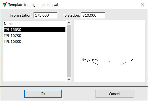
4. Define From station and To station values in order to define the station range for using this template.
5. Select a section template form the list of Section templates that is used for the given section range.
6. Click OK.
The template is added to the list in the Define alignment section templates dialog. You can continue with step 3 until templates for all station ranges are defined.
It is recommended to save the template list into a file that can be reloaded into the dialog. Select Save as command from the File menu to create a simple text file with the extension *.KLS.
7. Click on the Calculation button in the Define alignment section templates dialog.
This closes the list and opens the Compute Alignment Quantities dialog:
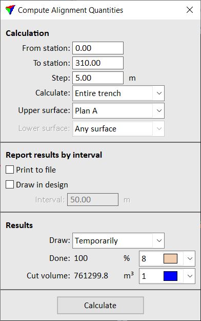
8. Define settings and click Calculate.
This starts the quantity computation. The results are displayed in the lower part of the Compute alignment dialog and possibly in the CAD file. If Print to file was selected in the first dialog, a standard Windows dialog opens to define the location for storing the text file on a hard disk.
Setting |
Effect |
|---|---|
From station |
Start station value for the quantity computation. |
To station |
End station value for the quantity computation. |
Step |
Defines the distance between consecutive section templates for the calculation. A small step produces more accurate results but the calculation process takes longer. |
Calculate |
Defines how to calculate the excavation related to existing surface models: •Entire trench - the quantity of excavation is computed for the area enclosed by a surface model and the trench boundaries defined by the section templates. •Layer - the quantities of excavation is computed for the area between two surface models and the trench boundaries defined by the section templates. |
Upper surface |
Name of the upper surface for quantity calculation. |
Lower surface |
Name of the lower surface for quantity calculation. This is only active if Calculate is set to Layer. |
Print to file |
If on, the results of the computation are saved into a simple text file. |
Draw into design |
If on, a linear scale of the alignment is drawn into the CAD file. The scale is divided into sections of the length defined by the Interval value. For each section, the rounded calculated cut volume value is displayed. |
Draw |
Display method for presenting the calculation results graphically in the CAD file: •Temporarily - temporary display of elements. Disappears if the tool is deactivated. •Permanently - draws permanent elements into the CAD file on the active level. |
Color list next to calculation result line |
Defines the display color for drawing the results in the CAD file. Uses the active color table of the CAD file. |