

TerraScan User Guide
Find Road Breaklines
 Find Road Breaklines tool is used for semi-automatic breakline detection along roads. The tool requires 2D line elements that run approximately along road breakline locations, for example close to the road center for crown of the road detection and close to the road edge for edge of pavement or curb stone detection. Based on that, the software searches the best 3D breakline close by.
The semi-automatic detection works for the following road breakline types:
•edge of pavement - runs along the edge of the road pavement.
•curb stone - runs along the curb stone edge of a road/sidewalk. A curb stone is defined as edge with a vertical elevation jump at the same XY location.
•crown of the road - runs along the crown of the road formed by a small slope change.
•planar surface
•section centerline - runs along the center of cross sections along the road.
•section breakline - runs along the edge of cross sections along the road.
The parameters for 3D breakline creation are defined for each breakline type.
The process requires dense laser points loaded in TerraScan. The laser points on the road surface should be classified into a separate class by using preferably the Hard surface classification routine. Further, the breakline placement along pavement edges benefits from color values assigned to the laser points.
After automatic breakline detection, you probably need to check and manipulate the breaklines manually.
To find road breaklines:
1. Load laser points into TerraScan. Only points in the class for road breakline detection are required.
2. Select Find Road Breaklines tool.
This opens the Find Road Breaklines dialog:
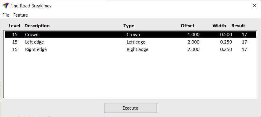
3. Select Add command from the Feature pulldown menu in order to define a new feature for road breakline detection.
You can modify an existing feature by selecting the feature and using the Edit command from the Feature pulldown menu. To delete a feature, select the Delete command from the Feature pulldown menu.
Add and Edit commands open the Road Feature dialog. The settings in the Road Feature dialog partly depend on the selected breakline type.
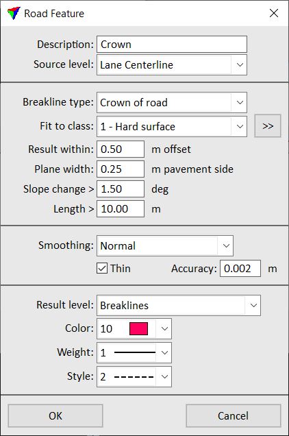
4. Define settings and click OK.
The feature is added to the list in the Find Road Breaklines dialog.
5. Repeat steps 3 to 4 for all road breakline features you want to detect.
6. (Optional) Save the road feature definitions into a text file using the Save as command from the File pulldown menu. You can save changes to an existing text file by selecting the Save command from the File pulldown menu.
7. Click Execute in order to run the breakline detection.
This starts the breakline detection process. The software draws breakline elements if it finds the 3D location of the breakline features in the loaded laser points.
SETTING |
EFFECT |
|---|---|
Description |
Descriptive name of the road feature. |
Source level |
CAD file level, on which the line elements are drawn that define the approximate location of the breakline feature. |
Breakline type |
Type of the breakline feature: •Crown of the road - runs along a small slope change. •Left curb stone - runs along a curb stone on the left side of a road. •Right curb stone - runs along a curb stone on the right side of a road. •Left edge of pavement - runs along the edge of pavement on the left side of a road. •Right edge of pavement - runs along the edge of pavement on the right side of a road. •Planar surface •Section centerline - runs along the center of cross sections along the road. •Section breakline - runs along the edge of cross sections along the road. |
Fit to class |
Point class that contains points on the road surface. Used for breakline detection. The list contains the active classes in TerraScan. |
|
Opens the Select classes dialog which contains the list of active classes in TerraScan. You can select multiple source classes from the list that are then used in the Fit to class field. |
Result within |
Maximum horizontal offset between the approximate line element and the true breakline location. This is not available if Breakline type is set to Left curb stone or Right curb stone. |
Plane width |
Width of a plane next to the breakline location. One value applies for the left and right side for Crown of the road and Planar surface features. There are two values for Left/Right edge of pavement features, one for the pavement side and another for the outside-road side. This is not available if Breakline type is set to Section centerline or Section breakline. |
Slope change |
Minimum change in slope gradient. Given in degree. This is only available if Breakline type is set to Crown of road. |
Length |
Minimum length of a breakline element. This is only available if Breakline type is set to Crown of road. |
Use color |
If on, the software uses RGB color values assigned to laser points in order to find the breakline location. This is only available if Breakline type is set to Left/Right edge of pavement. |
Fit tolerance |
Tolerance value for fitting the breakline element into the laser points. Relates to the noise in the data. This is only available if Breakline type is set to Section centerline. |
Step |
Distance between consecutive cross sections along the road used for fitting the line element to the laser points. This is only available if Breakline type is set to Section centerline. |
Percentile |
This is only available if Breakline type is set to Section centerline. |
Max offset |
Maximum horizontal offset between the approximate line element and the true breakline location. This is only available if Breakline type is set to Section breakline. |
Smoothing |
Defines the degree of smoothing applied to a breakline element: •None - no smoothing. •Normal - a bit smoothing. •Aggressive - maximum smoothing. |
Thin |
If on, a vertex is removed, if the location of the line does not change more than the given value. |
Result level |
CAD file level on which the breakline elements are drawn. |
Color |
Color of the breakline elements. Uses the active color table of the CAD file. |
Weight |
Line weight of the breakline elements. Uses the standard line weights of the CAD file. |
Style |
Line style of the breakline elements. Uses the standard line styles of the CAD file. |
