

TerraScan User Guide
Check Footprint Polygons
 Check Footprint Polygons tool compares building footprint polygons with point cloud data, usually with points classified into building class. The software computes the percentage of each polygon covered by point cloud data and the optimal rotation of a polygon in order to match the point cloud data best. The rotation computation considers the roof structure where the normal vector of the roof planes effect the footprint polygon rotation. There are two methods implemented in the tool:
•Check as list - the software offers a list of footprint polygons and the results of the comparison with point cloud data. The user can check the footprints by going through the list. The list dialog also offers modification tools for improving the footprint polygons.
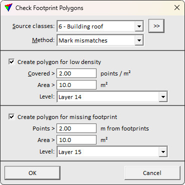
•Mark mismatches - the software marks areas with problems between footprint polygon and point cloud data. It may create polygons that mark areas of low point density (footprint is not covered with points) and areas of missing footprints (no footprint for points classified as building).
The tool is useful for finding flaws in the building classification, places with no or very sparse laser points on building roofs, and flaws in building footprint vector data. It's recommended to be used before the footprint polygons are used in automatic building vectorization.
To compare footprint polygons and laser data:
1. Load laser data into TerraScan. Only points in class(es) for the comparison with footprint polygons are required.
2. Select the footprint polygons that you want to include in the comparison.
3. Select the Check Footprint Polygons tool.
This opens the Check Footprint Polygons dialog:
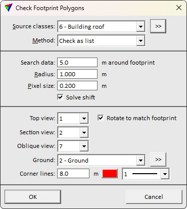
4. Define settings and click OK.
The comparison starts and the software creates either a list of comparison results for each footprint or polygons that mark problematic areas.
SETTING |
EFFECT |
|---|---|
Source classes |
Point class(es) used for the comparison. The list contains the active classes in TerraScan. |
|
Opens the Select classes dialog which contains the list of active classes in TerraScan. You can select multiple source classes from the list that are then used in the Source classes field. |
Method |
Method for handling comparison results: •Check as list - list dialog shows footprint polygons and offers tools for interactive modification of the polygons. •Mark mismatches - polygons drawn in the CAD file mark areas with problems. This determines the availability of further settings in the dialog. |
Search data |
Distance from the footprint boundary within which the software searches for point cloud data. |
Radius |
Circular area covered by a point. The value depends on the point density. |
Pixel size |
Size of a pixel for analyzing point coverage inside a polygon area. |
Solve shift |
Automatic footprint shift toggle. If on, solves automatic shift but processing time is longer. |
Top view |
Number of a CAD file view that is used to display the footprint area as top view. |
Rotate to match footprint |
If on, the top view is rotated horizontally in order to follow the base direction of the footprint. |
Section view |
Number of a CAD file view that is used to display the footprint area as section view. |
Oblique view |
Number of a CAD file view that is used to display a footprint on top of oblique images. This requires image data loaded in TerraPhoto. |
Ground |
Class used to turn a 2D footprint polygon into a 3D polygon. This is required for the display on top of oblique images in order to enable the comparison in 3D. Usually, points on the ground should be used. |
|
Opens the Select classes dialog which contains the list of active classes in TerraScan. You can select multiple source classes from the list that are then used in the Ground field. |
Corner lines |
Length, color and line weight of temporary vertical line elements that are drawn for building corners in oblique views. Click on the color field in order to select another color from the Windows Color dialog. Change the line weight by selecting another weight from the list. The list contains the standard line weights of the CAD file. |
Create polygons for low density |
If on, polygons are created on places where there is a selected polygon but no or only sparse laser points in the given Source class(es). |
Covered |
Defines the minimum point density inside a footprint polygon. If the density is lower, a polygon is created. |
Area |
Defines the minimum area of a building. Only areas larger than the given value are considered in the comparison. |
Level |
Polygons marking low density places are drawn on the given level using the active symbology settings of the CAD file. |
Create polygons for missing footprint |
If on, polygons are created on places where there are laser points in the given Source class(es) but no selected polygon. |
Points |
Defines the minimum distance between a laser point and a selected polygon. If the distance is larger, a polygon is created. |
Area |
Defines the minimum area of a building. Only areas larger than the given value are considered in the comparison. |
Level |
Polygons marking missing footprint places are drawn on the given level using the active symbology settings of the CAD file. |

Check Footprint Polygons results
If method Check as list is used for footprint polygon vs. point cloud data comparison, another Check Footprint Polygons dialog is opened to show the results:
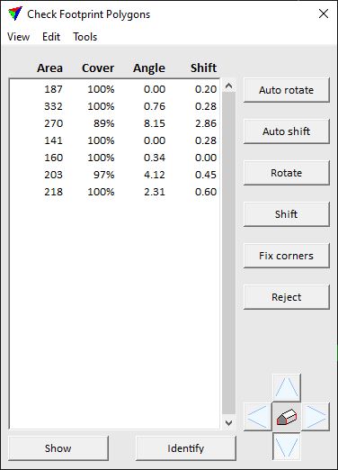
The dialog offers various options to modify and improve the footprint polygons.
Menu command/button |
EFFECT |
|---|---|
Auto rotate |
Derives a rotation for the polygon in order to fit it to the point cloud data. After clicking the button, move the mouse close to the footprint in the top view. The new position is shown. Place a data click in order to confirm the new position. |
Auto shift |
Derives a shift for the polygon in order to fit it to the point cloud data. After clicking the button, move the mouse close to the footprint in the top view. The new position is shown. Place a data click in order to confirm the new position. |
Rotate |
Lets you interactively rotate a polygon. Place a data click in the top view to determine the rotation center point. Move the mouse pointer to rotate the polygon. Confirm the new position with another data click. |
Shift |
Lets you interactively shift a polygon. Place a data click in the top view to determine the shift origin. Move the mouse pointer to shift the polygon. Confirm the new position with another data click. |
Fix corners |
Sets polygon corners to 90 degree angles. In the Fix Corners dialog, the user can define whether the edge positions are derived from the existing polygon or from the point cloud data. |
Reject |
Moves a polygon to another CAD file level. This button is defined in the Check Footprint Buttons dialog. |
Show |
Select a footprint polygon in the list and click on the Show button. Move the mouse pointer inside the top view. This highlights the corners of the selected polygon. Place a data click in order to center the polygon in the view. |
Identify |
Click on the Identify button and move the mouse pointer close to a footprint polygon in the top view. This highlights the polygon. Place a data click in order to center the polygon in the view and to select the corresponding row in the list of footprint polygons. |
|
Change between oblique images by clicking on one of the four buttons around the building icon. An oblique image that sees the building from the selected direction is displayed in the Oblique view. This requires image data loaded in TerraPhoto. |
File / Save list as |
Saves the list of footprint polygons into a text file. |
Set the display of fields in the Check Footprint Polygons dialog. |
|
View / Sort by |
Sort the list of footprint polygons in the Check Footprint Polygons dialog: •Area - size of the footprint area. •Corners - Number of non-90-degree corners. •Coverage - percentage of area covered with point cloud data. •Location - geographical location. •Angle - angular mismatch. •Shift - locational mismatch. |
Set the display of buttons and the action of user-defined buttons. |
|
Edit / ... |
The Edit menu contains commands that apply the same actions to polygons as the buttons described above: Auto rotate, Auto shift, Rotate, Shift, Fix corners. |
Move footprint polygons without point cloud data to another CAD file level. |
|
Create text elements that label footprint polygons. |
|
Apply fixes to all footprint polygons in the list if given conditions are fulfilled. |

Fields command from the View menu opens the View Footprint Fields dialog:
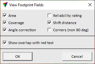
Switch on the attributes that you want to see in the list of the Check Footprint Buttons dialog. Click OK to apply changes in the settings.
Attribute |
Description |
|---|---|
Area |
Size of a footprint polygon. |
Coverage |
Area of the footprint polygon covered with point cloud data. Given in percentage. |
Angle correction |
Angular mismatch between the footprint polygon and the building in the point cloud data. |
Reliability rating |
Weight for computing the angle correction. The value determines how reliable a suggested rotation is. The higher the value, the better the auto rotation will match the polygon to the point cloud data. |
Shift distance |
Horizontal locational mismatch between the footprint polygon and the building in the point cloud data. |
Corners (non 90 deg) |
Number of corners that are not 90 degree. |
Show overlap with red text |
Footprint polygons that overlap each other are shown with red text in the list of the Check Footprint Buttons dialog. |
Buttons command from the View menu opens the Check Footprint Buttons dialog:
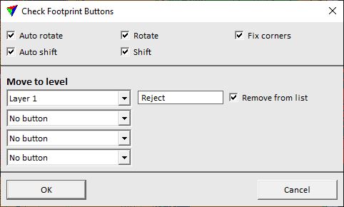
Switch on the buttons that you want to see in the Check Footprint Buttons dialog. You may define additional buttons for moving polygons to specific CAD file levels.
To define additional buttons:
1. Select a CAD file level from the selection list.
2. Type a name for the button in the text field.
3. Decide whether the footprint polygon is removed from the list in the Check Footprint Buttons dialog or not when the button is pressed.
4. Click OK in order to apply the changes to the button settings.
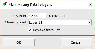
Tools / Mark missing data polygons
Mark missing data polygons command from Tools menu can be used to move footprint polygons to another CAD file level if there is not enough point cloud data in the building class. This may help to identify buildings for which the creation of 3D building models is problematic due to the lack of data. In general, a coverage of less than 50-60% is problematic for automatic vectorization processes.
The command opens the Mark Missing Data Polygons dialog:
Setting |
Effect |
|---|---|
Less than |
Minimal expected percentage of polygon area covered with points. If the percentage is lower, the polygon is identified as missing data area. |
Move to level |
Polygons identified as areas of missing data are moved to the given CAD file level. |
Remove from list |
If on, the footprint polygon is removed from the list in the Check Footprint Buttons dialog. |
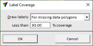
Label coverage command from the Tools menu creates text elements as labels for footprint polygons. The label shows the percentage of area that is covered with point cloud data. The text elements are drawn in the CAD file on the active level using the active text and symbology settings.
The command opens the Label Coverage dialog:
Setting |
Effect |
|---|---|
Draw labels |
Determines for which polygons the labels are created: •For all polygons - all polygons. •For missing data polygons - only polygons with a coverage defined by the Less than setting. |
Less than |
Minimal percentage of polygon area covered with points. Only if the percentage is lower, the polygon is labeled. This is active only if Draw labels is set to For missing data polygons. |
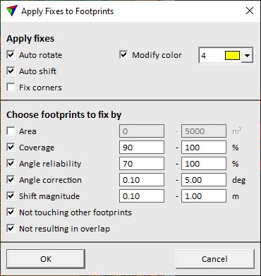
Apply fixes command from the Tools menu applies corrections to all footprint polygons that fulfill given conditions. The user defines what corrections to apply (rotation, shift, fix corners) and what conditions must be fulfilled. Only footprint polygons for which all conditions apply, are modified.
Settings |
effect |
|---|---|
Auto rotate |
If on, an angular correction is applied. |
Auto shift |
If on, an horizontal locational correction is applied. |
Fix corners |
If on, corners are fixed to 90 degree angles. |
Modify color |
If on, the given color is applied to the modified polygons. Select another color from the color selection list. |
Area |
Polygons are modified if their size is within the given range of squared CAD file units. |
Coverage |
Polygons are modified if they are covered by point cloud data within the given percentage range. |
Angle reliability |
Polygons are modified if their reliability value for angle correction is within the given percentage range. |
Shift magnitude |
Polygons are modified if the magnitude of the shift correction is within the given range of CAD file units. |
Not touching other footprints |
Polygons are modified if they do not touch another footprint polygon. |
Not resulting in overlap |
Polygons are modified if there is no overlap between footprint polygons caused by the modification. |