

TerraScan User Guide
Check Tunnel Sections
Not UAV
 Check Tunnel sections tool supports the systematic check of tunnel sections created by the Vectorize Tunnel Sections tool. It provides a list of tunnel sections from which you can select one element after the other.
The tool includes settings that define a CAD file section view displaying a selected tunnel section. The selected section is automatically centered in this view.
To check tunnel sections:
1. Select the alignment element that has been used for vectorizing the tunnel sections.
2. Select the Check Tunnel Sections tool.
This opens the Check Tunnel Sections dialog:
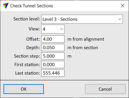
SETTING |
EFFECT |
|---|---|
Section level |
CAD file level on which the tunnel sections have been drawn. |
View |
CAD file view used for displaying the selected tunnel section in a section view. |
Offset |
Distance to the left and right from the alignment element that is displayed in the section view. |
Depth |
Distance forward and backward from the section centerline. Defines the depth of the section displayed in the section view. |
Section step |
Distance between consecutive sections. This should be the same value as used for vectorizing the tunnel sections. |
First station |
Location of the first section for display along the alignment element. By default, this is the starting point of the alignment element. |
Last station |
Location of the last section for display along the alignment element. By default, this is the end point of the alignment element. |
3. Define settings and click OK.
This opens another Check Tunnel Sections dialog that contains the list of all sections that belong to the selected alignment element:
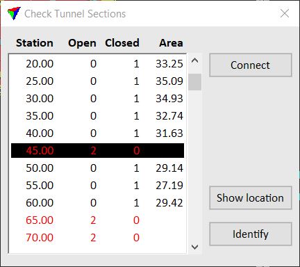
•Station - location of a tunnel section along the alignment element.
•Open - amount of gaps along the tunnel section line string. Entries with gaps are highlighted in red.
•Closed - amount of closed tunnel section line strings.
•Area - size of the area enclosed by the tunnel section line string. Given in CAD file units.
4. Select a row in the list of sections.
This centers the selected section in the CAD file view defined in the tool’s View setting.
SETTING |
EFFECT |
|---|---|
Connect |
Creates a connection line between open end points of the tunnel section line string. |
Show location |
Select a row in the list, click on the button and move the mouse pointer inside a CAD file view. This highlights the selected section location in the view. |
Identify |
Click on the button and identify an element with a data click in a CAD file view. This selects the corresponding row in the list. |
To close a gap in a tunnel section
1. Select the section in the Check Tunnel Sections dialog list.
2. Select the Connect button in the Check Tunnel Sections dialog.
3. Move the mouse pointer inside the CAD file section view close to the gap you want to close.
This shows a preview of the connection line.
4. Place a data click in order to confirm the connection line. Continue placing connection lines until all gaps are closed.
This connects the end points of the existing section line string, moves the section drawing to the active level of the CAD file and applies the active symbology settings. The entry in the Check Tunnel Sections dialog list is updated.
You may use other CAD tools to modify tunnel sections as well. This is not updating the list in the Check Tunnel Sections dialog automatically.