

TerraPhoto User Guide
Camera Views
Camera views are perspective views where the location of the observer (= camera) and the target are defined. This can be useful, for example, to analyze the visibility of objects from a certain location. Camera views are created using the camera settings of Bentley CAD or Spatix.
Note that camera views described in this section do not serve the same purpose as camera views of TerraPhoto, which are used as a first step to solve camera parameters. See Create camera view command for more information.
Bentley CAD
To create a camera view:
1. Select View Control command from the Tools pulldown menu in Bentley CAD.
This opens the View Control menu.
 2. Select the Camera Settings tool.
This opens the Camera Settings dialog:
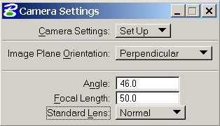
3. Place a data click inside a view to define the view for camera view display. The settings in the lower part of the dialog become active.
4. (Optional) Change settings for the camera. For more information about camera settings refer to the Bentley CAD documentation.
5. Place a data click inside the view to define the target point of the camera.
6. Place a data click inside the view to define the camera location.
This displays the camera view.
It might be helpful to start the camera view creation from a top view that shows, for example, orthophotos. To define exact coordinates for the camera location and the target point, Bentley CAD AccuDraw can be used to set absolute coordinate values.
Another possibility is to set the height of camera location and target point based on a ground model. The ground model can be represented by laser points loaded into TerraScan or by a surface model loaded in TerraModeler.
To create a camera view using a ground model:
1. Load points representing the ground into TerraScan.
OR
1. Create a surface model with TerraModeler.
2. Select Camera Settings tool as described above.
3. Place a data click inside a view to define the view for camera view display.
4. Select Mouse Point Adjustment tool from the Drawing tools in TerraScan.
OR
4. Select View elevation tool from the Draw using Surface tools in TerraModeler.
5. In the Mouse Point Adjustment dialog, lock Adjust elevation and set a value for Dz. The value defines the height above the laser points for each mouse click. Select also a laser point class in the Class field.
OR
5. In the View elevation dialog, lock Points on surface and set a value for Dz. The value defines the height above the surface model for each mouse click. Select also a surface model in the Surface field.
6. Place a data click inside the view to define the target point of the camera.
7. (Optional) Change the value for Dz in the Mouse Point Adjustment dialog or View elevation dialog to set another height for the camera location.
8. Place a data click inside the view to define the camera location.