

TerraPhoto User Guide
Draw into design
Draw into design command draws the trajectories as line elements into the CAD file. The line elements are drawn on the active level using the active line width and style settings of the CAD file. The color(s) of the line elements are defined by the command’s settings.
The command can use accuracy values that are assigned to trajectory positions. See Import accuracy files for more information.
The line elements are drawn by placing a vertex for each trajectory position. The lines can by simplified by removing positions within a given tolerance.
To draw trajectory lines into the CAD file:
1. (Optional) Select trajectory file(s) to draw.
2. Select Draw into design command from the Tools pulldown menu.
This opens the Draw trajectories dialog:
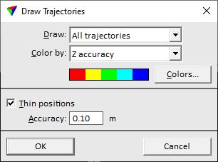
3. Define settings.
SETTING |
EFFECT |
|---|---|
Draw |
Trajectories that are drawn: •All trajectories - all trajectories in the list. •Selected only - selected trajectories only. |
Color by |
Determines how the color is chosen for drawing a trajectory line: •Active color - the active color of the CAD file is used. •Trajectory number - the color whose number in the active color table of the CAD file corresponds to the trajectory number is used. •Xy accuracy - x/y accuracy values are applied to a color scheme. •Z accuracy - z accuracy values are applied to a color scheme. •H accuracy - heading accuracy values are applied to a color scheme. •Rp accuracy - roll/pitch accuracy values are applied to a color scheme. |
Colors |
Button to open the coloring scheme for accuracy-based coloring methods. |
Thin positions |
If on, intermediate trajectory positions are skipped when the line is drawn as long as the line accuracy stays within the given positional Accuracy tolerance. |
4. If the trajectory is drawn with an accuracy-based coloring option, click on the Colors button.
This opens the Coloring scheme dialog:
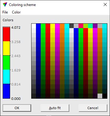
5. (Optional) Define your own coloring scheme for drawing trajectories.
6. Click on the Auto fit button in order to fit the colors to RMS value ranges.
7. Click OK to the Coloring scheme dialog.
8. Click OK to the Draw trajectories dialog.
This draws the line element(s) into the CAD file.
You can undo the drawing of trajectories by using the Undo command of the CAD platform.