

TerraPhoto User Guide
Define tie points
Not Lite
Define tie points command switches the application into tie point mode. This involves building a triangulated model of the ground (if available) and re-arranging the views for the work with tie points.
There are two entry modes for tie points. The "Ortho image" entry mode should be used if a ground model is available. Then, images are referenced on the ground model and ground tie point placement is possible. This is the preferred entry mode for airborne missions and orthophoto production. The "Raw image" entry mode should be used if no ground model is available. The depths settings for this mode determine the depths range from the camera in which tie points can be placed. This entry mode is more common for mobile missions and MMS imagery.
The processing workflow and all commands related to tie points are described in detail in Chapter Working with Tie Points.
To start the tie points mode:
1. Select Define tie points command from the Images pulldown menu.
This opens the Tie point entry mode dialog:
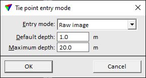
2. Select the entry mode and additional settings, if necessary.
SETTING |
EFFECT |
|---|---|
Entry mode |
Tie point entry mode: •Ortho image - images are rectified on a ground surface. This requires ground points loaded into TerraPhoto. •Raw image - images are not rectified. No ground model is required. |
Max mismatch |
Estimate of the maximum mismatch between images. This effects the semi-automatic tie point placement. Tie points are rejected if the mismatch exceeds the given limit. This is only active if Entry mode is set to Ortho image. |
Default depth |
Default distance between the camera and a raw image for placing tie points. Approximate flight altitude (aerial images) or distance from the camera to objects in the surrounding (mobile images). This is only active if Entry mode is set to Raw image. |
Maximum depth |
Maximium distance between the camera and a raw image for placing tie points. This is only active if Entry mode is set to Raw image. |
3. Click OK.
This might open the Tie point view setup dialog, unless the view setup has been saved for the CAD file before.
4. Define view setup settings and click OK. See Setup command for more information about the view setup.
The software reorganizes the CAD file views according to the setup settings. It also opens the Tie points window which contains the active image list. The functionality of the windows and dialogs is introduced in section Tie point entry windows.
If the Tie points window is closed, the CAD file views used for tie point processing are closed as well. The view setup switches back to the same arrangement that had been active before the tie point mode was started. However, the tie points are still active and loaded in the memory.