

TerraPhoto User Guide
Color Points and Selection Shapes
The commands in the Color points menu provide methods for improving the quality of rectified image or colored point clouds. Besides color points, there are several types of correction shapes (called selection shapes) which can be placed using tools from the menu.
When you select Define color points command from the Rectify pulldown menu in the TPhoto window, the applications changes to color point mode. There are two modes available:
•Ground ortho - for rectified images or orthophotos.
•Point cloud - for colored point clouds, especially mobile laser scanning point clouds.
Color points for image rectification require a ground model loaded in TerraPhoto. The mode can not be selected, if there is no ground model available. If the color point mode starts, the software builds a triangulated ground model, opens the Color points menu for Ground ortho color points, and displays a preview of the ortho mosaic in a CAD file top view.
Color points for point clouds require a TerraScan project that manages the point cloud and a point cloud format that is able to store color values, image numbers, and normal vectors/dimensions for each point. The storage of all these attributes is only possible in TerraScan FastBinary format. If the color point mode starts, the software sets up the display mode for laser points, extracts on-the-fly color values for the points, and opens the Color points menu for Point cloud color points.
The color point mode is closed when the Color points menu is closed.
The software uses thumbnails for the preview of the orthophoto mosaic in color point mode. The thumbnails must be stored in the \TEMP folder of the mission. See Create thumbnails for more information.
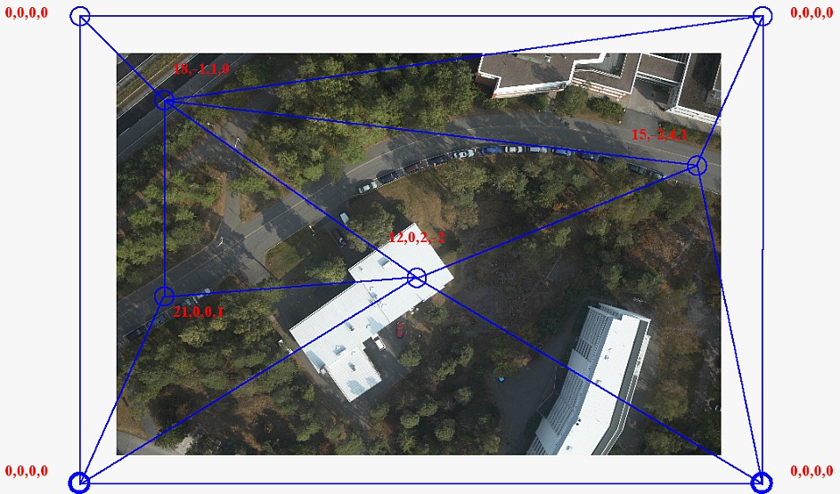
Color points form a triangulated correction model where each color point provides intensity (brightness) correction and color balance corrections for up to 10 channels at the point’s xy location. The correction model for rectified images is illustrated in the figure below.
Color points are stored in text files with the extension .CPT. The files includes the following information:
•for each color point: type, xyz coordinate values in current projection system, radius, intensity value, values for 10 color channels, for Point cloud color points XYZ components of the normal vector
•for each image: weight, average intensity value, values for 10 color channels, color point xy coordinates in image pixels
The xyz coordinate values are recomputed whenever necessary. You do not need to apply coordinate transformations to color points.
When color points are loaded in memory, they are drawn temporarily as circle elements on a CAD file level. The level and color for drawing color points are defined in Color points of TerraPhoto Settings. The drawing disappears if the Color points menu is closed.
Color points can be placed manually or automatically. The automatic method first searches for a large number of potential color points. Then, it rates each point by checking if the point is needed and fits into the correction model. Finally, the best points are selected. After an automatic search, the color points should be checked and possibly filtered. There are manual editing options as well as automatic methods for filtering out bad color points.
There are several types of color points according to the method of color correction computation:
•Average - intensity and color values are averaged from all images at the color point location. This is the method used for automatically placed Point cloud color points.
•Grey average - color values are balanced in order to get the averaged gray value.
•Fixed - hue, saturation, and value (HSV color model) components of the color point can be set to fixed values. This type can be placed only manually.
•Reference - colors from reference images are use for target color calculation. Requires an image attached as TerraPhoto reference at the location of color point. This type can be placed only manually.
If object shapes are available, they can be used for Ground ortho color points on roof tops. The process can also use shadow maps in order to determine locations where trees or other objects cause shadow effects. See Compute shadow maps for more information.
Selection shapes are correction polygons that improve the quality of the final orthophoto mosaic or colored point cloud. Basically, they manipulate the seamlines (boundaries) between adjacent raw images in the orthophoto mosaic or specify certain images for being used in areas defined by the selection shapes.
Common problems in orthophoto mosaics from airborne image data are large objects, like buildings, cut by seamlines; small objects, like trees or cars cut by seamlines; areas with differences in structure, brightness, texture, etc., such as water under changing light conditions; images from different altitudes. In image data of ground-based mobile systems, most problems are related to moving objects, for example cars on a road, that are visible in some of the raw images.
Most issues in ground-based mobile point clouds are caused by the changing light conditions for the different cameras and by moving objects.
Selection shapes are distinguished into different types:
•Selection shapes - specify one image to be used inside the shape. Good for larger objects, such as buildings, that are cut by raw image boundaries. For Point clouds, also colors from multiple images of one line can be used inside the shape.
•Quality shapes - specify an area within which only images with a given quality number are used for rectification. Useful, for example, if images from two altitudes and with different qualities are available. In images from mobile systems, quality shapes can be used to exclude cars or other moving objects by using images from another drive path. Available in Ground ortho mode only.
•Smearing shapes - specify an area close to raw image boundaries, where pixels are blurred. Good for water surfaces with sun reflexions or fields with low vegetation. Available in Ground ortho mode only.
•Auto seamline shapes - specify one image to use inside a small shape. Good for small objects, like trees or cars in airborne data sets. Available in Ground ortho mode only.
•Shadow shapes - specify shadow areas in point clouds. Available in Point cloud mode only.
Auto seamlines are created automatically, all other types of selection shapes are placed manually. All types of shapes in Ground ortho mode are drawn as shape elements into the CAD file. They can be edited with CAD platform tools. Symbology settings of selection shapes can be defined in Selection shapes of TerraPhoto Settings.
Shapes in Point cloud mode are only drawn temporarily. Selection shapes manipulate the image assignment stored for the laser points. Shadow shapes effect the color points.